
High-voltage electric appliance contact finger part cold extrusion forming technology and die thereof

A technology for high-voltage electrical appliances and forming processes, applied in metal extrusion dies, electrical components, metal material coating processes, etc., can solve the problems of insufficient filling at the ear making, difficulty in forming finger parts, and low material utilization. Achieve the effect of easy molding, stable mechanical properties and high processing efficiency

Pending Publication Date: 2021-04-16
玉环市东南塑胶机电有限公司
View PDF5 Cites 0 Cited by
  • Summary
  • Abstract
  • Description
  • Claims
  • Application Information

AI Technical Summary

Problems solved by technology

[0002] The contact finger parts of high-voltage electrical appliances are the key core parts of high- and medium-voltage electrical appliances. The shape of the finger parts is generally more complicated. The use of milling division, CNC machining and other processes will result in low material utilization and large waste. Therefore, the batch of contact finger parts The production generally uses rods or plates for cold extrusion production. This production process makes the material utilization rate high and the waste is less. However, the technical nature of the cold extrusion process itself leads to high metal fluidity during processing, which will affect the formation of finger parts. Some difficulties are caused, that is, the existing cold extrusion forming process of finger parts makes it difficult for the metal at one end of the material to transfer through the bending part in the middle, making it difficult to completely fill the other end, and the parts tend to form larger flying parts. The edge, the filling of the ear is not full

Method used


Image

  • High-voltage electric appliance contact finger part cold extrusion forming technology and die thereof
  • High-voltage electric appliance contact finger part cold extrusion forming technology and die thereof
  • High-voltage electric appliance contact finger part cold extrusion forming technology and die thereof

Examples


Embodiment 1

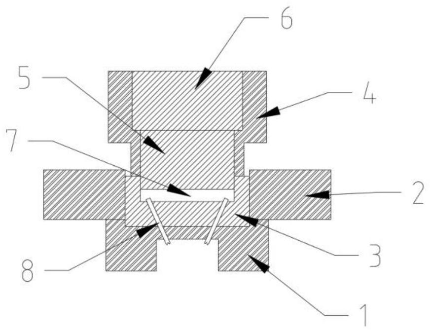
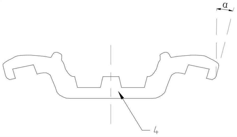
[0046] Embodiment 1: Using a mold of a cold extrusion forming process for high-voltage electrical contact finger parts to prepare contact finger parts, wherein the draft angle of the cavity 7 is 2.5°, including the following steps:

[0047]S1. Material selection and cutting: Select T2 red copper that matches the target size of the finger parts, cut it, and the volume is 1021mm 3 ;

[0048] S2. Annealing treatment:

[0049] 1) The first heating and holding stage: the temperature is raised from room temperature to 200°C, the heating rate is 3°C / min, and the holding time is 3h;

[0050] 2) The second heating and holding stage: from the first heating and holding stage to 390°C, the heating rate is 2.2°C / min, and the holding time is 3.5h;

[0051] 3) Cooling: take out after cooling to 65°C from the second heating and holding stage;

[0052] S3. Phosphating treatment:

[0053] 1) Phosphating treatment: place the blank in a phosphating solution for phosphating, the phosphating ti...

Embodiment 2

[0061] Embodiment 2: Using a mold of a cold extrusion forming process for high-voltage electrical contact finger parts to prepare contact finger parts, wherein the draft angle of the cavity 7 is 2.2°, including the following steps:

[0062] S1. Material selection and cutting: Select T2 red copper that matches the target size of the finger parts, cut it, and the volume is 1021mm 3 ;

[0063] S2. Annealing treatment:

[0064] 1) The first heating and holding stage: the temperature is raised from room temperature to 180°C, the heating rate is 2.4°C / min, and the holding time is 2.5h;

[0065] 2) The second heating and holding stage: from the first heating and holding stage, the temperature is raised to 370°C, the heating rate is 2°C / min, and the holding time is 3h;

[0066] 3) Cooling: take out after cooling to 50°C from the second heating and holding stage;

[0067] S3. Phosphating treatment:

[0068] 1) Phosphating treatment: place the billet in a phosphating solution for ...

Embodiment 3

[0076] Embodiment 3: Using a mold of a cold extrusion forming process for high-voltage electrical contact finger parts to prepare contact finger parts, wherein the draft angle of the cavity 7 is 2.8°, including the following steps:

[0077] S1. Material selection and cutting: Select T2 red copper that matches the target size of the finger parts, cut it, and the volume is 1021mm 3 ;

[0078] S2. Annealing treatment:

[0079] 1) The first heating and holding stage: the temperature is raised from room temperature to 220°C, the heating rate is 3.6°C / min, and the holding time is 3.5h;

[0080] 2) The second heating and holding stage: from the first heating and holding stage to 420°C, the heating rate is 2.4°C / min, and the holding time is 4h;

[0081] 3) Cooling: take out from the second heating and holding stage after cooling to 80°C;

[0082] S3. Phosphating treatment:

[0083] 1) Phosphating treatment: place the billet in a phosphating solution for phosphating, the phosphat...


PUM

PropertyMeasurementUnit
Draft angleaaaaaaaaaa

Abstract

The invention discloses a high-voltage electric appliance contact finger part cold extrusion forming technology and a die thereof. The high-voltage electric appliance contact finger part cold extrusion forming technology comprises the steps of material selection and cutting, annealing treatment, phosphating treatment, cold extrusion forming, hot isostatic pressing treatment, edge cutting and tumbling. According to the die of the high-voltage electric appliance contact finger part cold extrusion forming technology, a female die is arranged in a stress outer ring, a male die outer ring is arranged at the upper end of the female die, a male die is arranged in the male die outer ring, a cavity is formed between the female die and the male die, and the cavity is axisymmetric and is a two-chamber cavity in the axisymmetric communication mode. According to the technology and the die, annealing treatment, cold extrusion forming and hot isostatic pressing treatment are combined, so that the metal transfer forming difficulty is reduced; meanwhile, formation of burrs is reduced to a great extent through the axisymmetric cavity and a rotatable inclined punch, the lug manufacturing position is filled fully, and the part yield is high.

Description

technical field [0001] The invention relates to the technical field of contact finger parts technology application, in particular to a cold extrusion forming process and mold for contact finger parts of high-voltage electrical appliances. Background technique [0002] The contact finger parts of high-voltage electrical appliances are the key core parts of high- and medium-voltage electrical appliances. The shape of the finger parts is generally more complicated. The use of milling division, CNC machining and other processes will result in low material utilization and large waste. Therefore, the batch of contact finger parts The production generally uses rods or plates for cold extrusion production. This production process makes the material utilization rate high and the waste is less. However, the technical nature of the cold extrusion process itself leads to high metal fluidity during processing, which will affect the formation of finger parts. Some difficulties are caused,...

Claims


Application Information

Patent Timeline
IPC IPC(8): B21C23/00B21C25/02B23P15/00H01H11/04C22F1/08C23C22/73C23C22/13
Inventor 周榆淘周超管俊放
Owner 玉环市东南塑胶机电有限公司
Learn More