A tool and method for measuring the accuracy of the c-axis angle of a turn-milling compound machining center

A compound machining center and shaft angle technology, which is applied in metal processing equipment, metal processing machine parts, manufacturing tools, etc., can solve the problems of undetectable, unrotatable axis positioning accuracy, correction and compensation, etc., and achieve saving inspection, simple and fast Effect of Detection and Correction Methods

Active Publication Date: 2018-03-13
JIANGXI CHANGHE AVIATION IND
View PDF7 Cites 0 Cited by
  • Summary
  • Abstract
  • Description
  • Claims
  • Application Information

AI Technical Summary

Problems solved by technology

Because the laser interferometer and the rotating shaft angle measuring head are very expensive, the general users will not purchase this set of instruments, so it is impossible to correct and compensate the positioning accuracy of the rotating shaft, so the risk is relatively large when the accuracy requirements are high, especially It is the replacement of the position detection part of the rotating shaft that needs to be detected but cannot be detected

Method used


Image

  • A tool and method for measuring the accuracy of the c-axis angle of a turn-milling compound machining center

Examples


Embodiment Construction

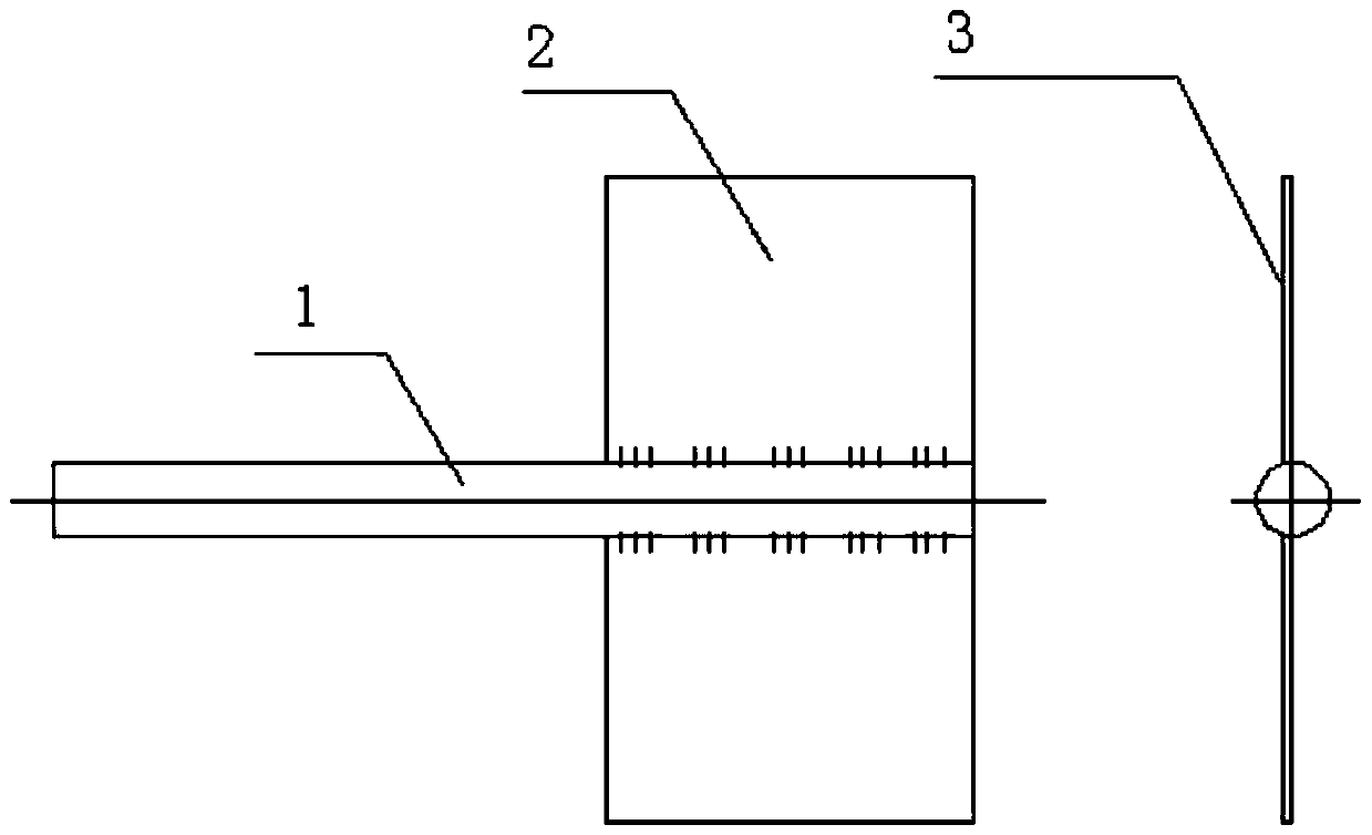
[0012] Reference attached figure 1 , the tooling of the present invention includes a round bar 1 and a flat plate 2. One end of the round bar 1 is provided with a stepped plane along the axial direction of the round bar.

[0013] One end of the round rod 1 can also be provided with parallel grooves, and the flat plate 2 can be installed and fixed in the parallel grooves along the axial direction of the round rod.

[0014] The present invention also provides a method for measuring the accuracy of the C-axis angle of the turning-milling compound machining center, which is characterized by comprising the following steps:

[0015] Step 1, self-made a set of tooling, the tooling includes a round rod and a flat plate, a step plane is milled out along the axis of the round bar at one end of the round bar, the flat plate is fixed on the step plane of the round bar, and the other side is ground Machining, as the reference measurement surface;

[0016] Step 2: Position the C-axis of t...


PUM


Abstract

The invention provides a tool for measuring the angle accuracy of a C-shaft of a turn-milling machining center. The tool is characterized by comprising a round bar (1) and a panel (2), wherein one end of the round bar (1) is provided with a step plane in the axial direction of the round bar; one face of the panel is fixed to the step plane of the round bar; and the other face of the panel serves as a standard measuring plane (3).

Description

technical field [0001] The invention belongs to the technical field of machine tool detection, and relates to a tool and a method for measuring the accuracy of the C-axis rotation angle of a turning-milling compound machining center. Background technique [0002] At present, the turning and milling compound machining center is more and more widely used, and the positioning accuracy of the machine tool needs to be calibrated and compensated regularly. The calibration and compensation method generally uses a laser interferometer. Using a laser interferometer to check the positioning accuracy of a linear axis is very simple and does not require additional fixtures, but it is extremely difficult to use a laser interferometer to check and correct the positioning accuracy of a rotary axis. Checking and correcting the positioning accuracy of the rotary axis requires an additional rotary axis angle probe. Because the laser interferometer and the rotating shaft angle measuring head ...

Claims


Application Information

Patent Timeline
Patent Type & Authority Patents(China)
IPC IPC(8): B23Q17/00
Inventor 林超青胡辉王景雨戴秋华周小峰李士学黎雪明蔡志杰冯正武李涛崔松
Owner JIANGXI CHANGHE AVIATION IND
Why Eureka
Try Eureka