Mechanical arm for laminating transformer cores

A transformer core and manipulator technology, applied in manipulators, inductance/transformer/magnet manufacturing, program control manipulators, etc., can solve problems such as low efficiency and unstable lamination quality, and achieve the effect of high-precision lamination

Inactive Publication Date: 2016-06-08
SHENYANG INST OF AUTOMATION - CHINESE ACAD OF SCI
View PDF6 Cites 26 Cited by
  • Summary
  • Abstract
  • Description
  • Claims
  • Application Information

AI Technical Summary

Problems solved by technology

[0003] There is no automatic mechanical device available in China to complete this process. At present, the lamination process of the transformer is completed in a group of six people. This method is not only inefficient, but also the lamination quality is unstable.

Method used


Image

  • Mechanical arm for laminating transformer cores
  • Mechanical arm for laminating transformer cores
  • Mechanical arm for laminating transformer cores

Examples


Embodiment Construction

[0034] In order to make the object, technical solution and advantages of the present invention clearer, the present invention will be described in detail below in conjunction with the accompanying drawings and specific embodiments.

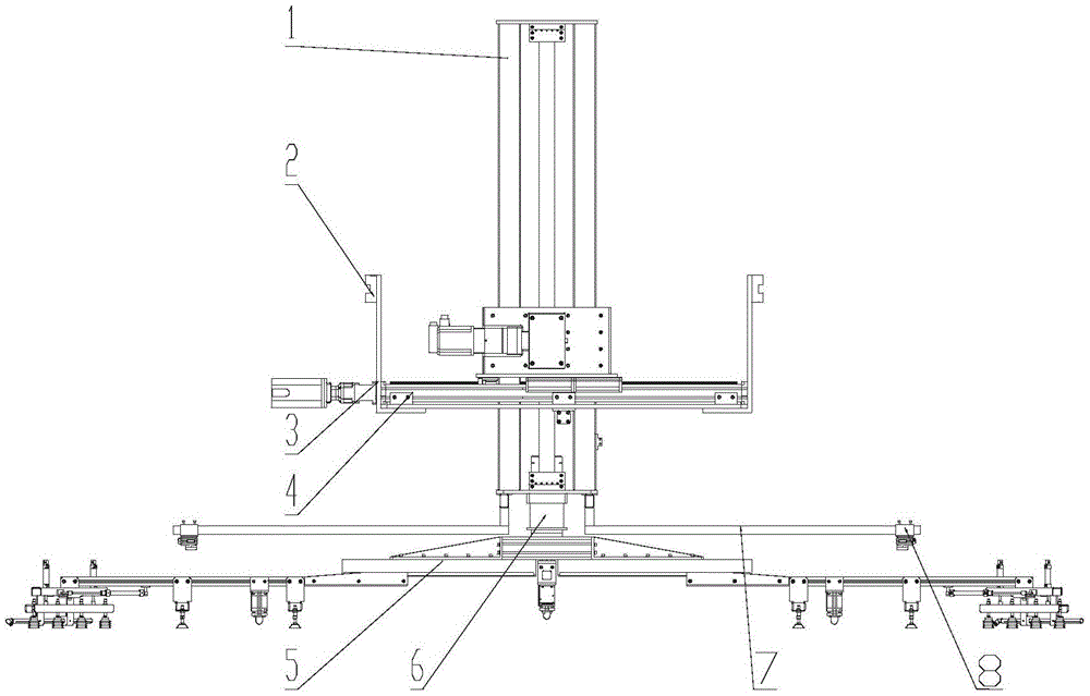
[0035] figure 1 It is a schematic diagram of the overall structure of the present invention; as figure 1 As shown, a transformer core lamination manipulator provided by the present invention includes a Y-direction movement component 1, a slider 2, a connecting plate 3, an X-direction movement component 4, a retractable suction cup type manipulator 5, a rotary movement component 6, a vision Camera bracket 7 and visual camera 8, wherein Y direction motion component 1 is connected with X direction motion component 4 slidingly, described rotary motion component 6 is installed on the lower end of Y direction motion component 1, and described retractable sucker type manipulator 5 is fixedly installed on Below the rotary motion assembly 6, the visual ca...


PUM

PropertyMeasurementUnit
thicknessaaaaaaaaaa

Abstract

The invention belongs to the technical field of transformer core lamination processes and particularly relates to a mechanical arm for laminating transformer cores. The mechanical arm comprises a Y-direction moving assembly, slide blocks, a connecting plate, an X-direction moving assembly, an extendable-and-retractable suction disc type mechanical arm body, a rotation movement assembly, a vision camera support and vision cameras, wherein the Y-direction moving assembly is connected with the X-direction moving assembly, the rotation movement assembly is mounted at the lower end of the Y-direction moving assembly, the extendable-and-retractable suction disc type mechanical arm body is fixed to the position below the rotation movement assembly, the vision camera support is mounted at the bottom of the Y-direction moving assembly, the vision cameras are fixedly mounted on the vision camera support, the connecting plate is fixedly connected with the bottom of the X-direction moving assembly and connected with a guide rail on a gantry through the slide blocks, and in this way, the mechanical arm for laminating the transformer cores can move in the Z direction. By means of the mechanical arm, the lamination process can be automated, efficiency of the process is improved, and a transformer product can achieve high quality.

Description

technical field [0001] The invention belongs to the technical field of transformer iron core lamination technology, in particular to a transformer iron core lamination manipulator. Background technique [0002] The stacking process of silicon steel sheets is an important link in the production of transformers. The thickness of silicon steel sheets is only 0.23mm to 0.3mm, and the stacking process consumes a lot of man-hours and manpower. The quality of lamination will also directly affect performance indicators such as transformer no-load and noise. Therefore, the stacking efficiency and stacking quality of transformer silicon steel sheets are very important in the entire transformer production process. [0003] There is no automatic mechanical device available in China to complete this process. At present, the lamination process of transformers is completed in a group of six people. This method is not only inefficient, but also the lamination quality is unstable. Contents...

Claims


Application Information

Patent Timeline
Patent Type & Authority Applications(China)
IPC IPC(8): B25J9/00B25J15/06H01F41/02H01F27/245
CPCB25J9/0009B25J15/0616H01F41/0233
Inventor 曹田野徐志刚刘勇昌成刚
Owner SHENYANG INST OF AUTOMATION - CHINESE ACAD OF SCI
Why Eureka
Try Eureka