
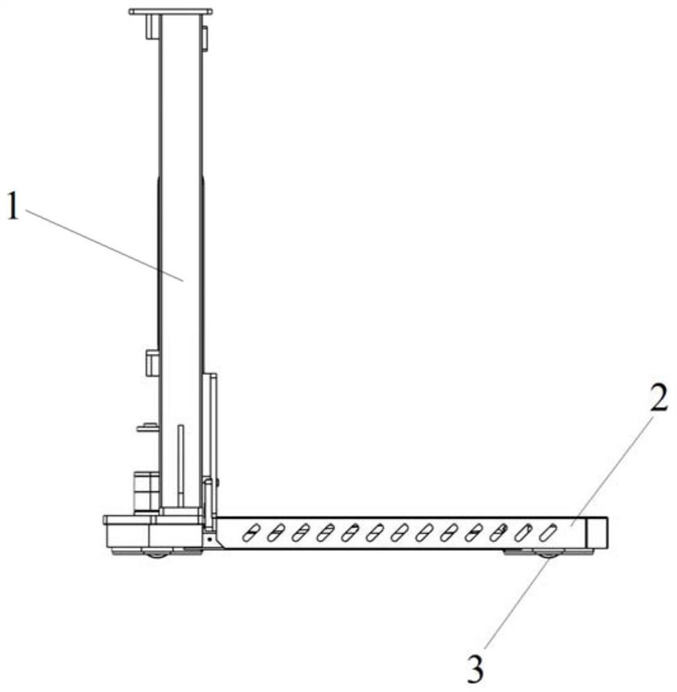
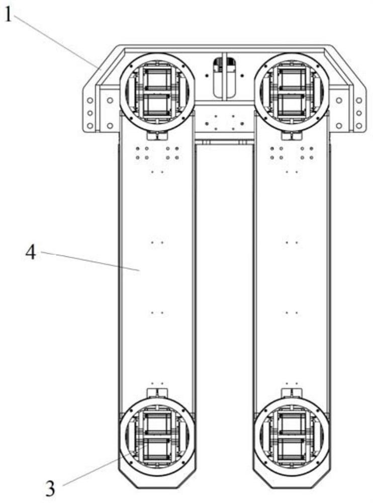
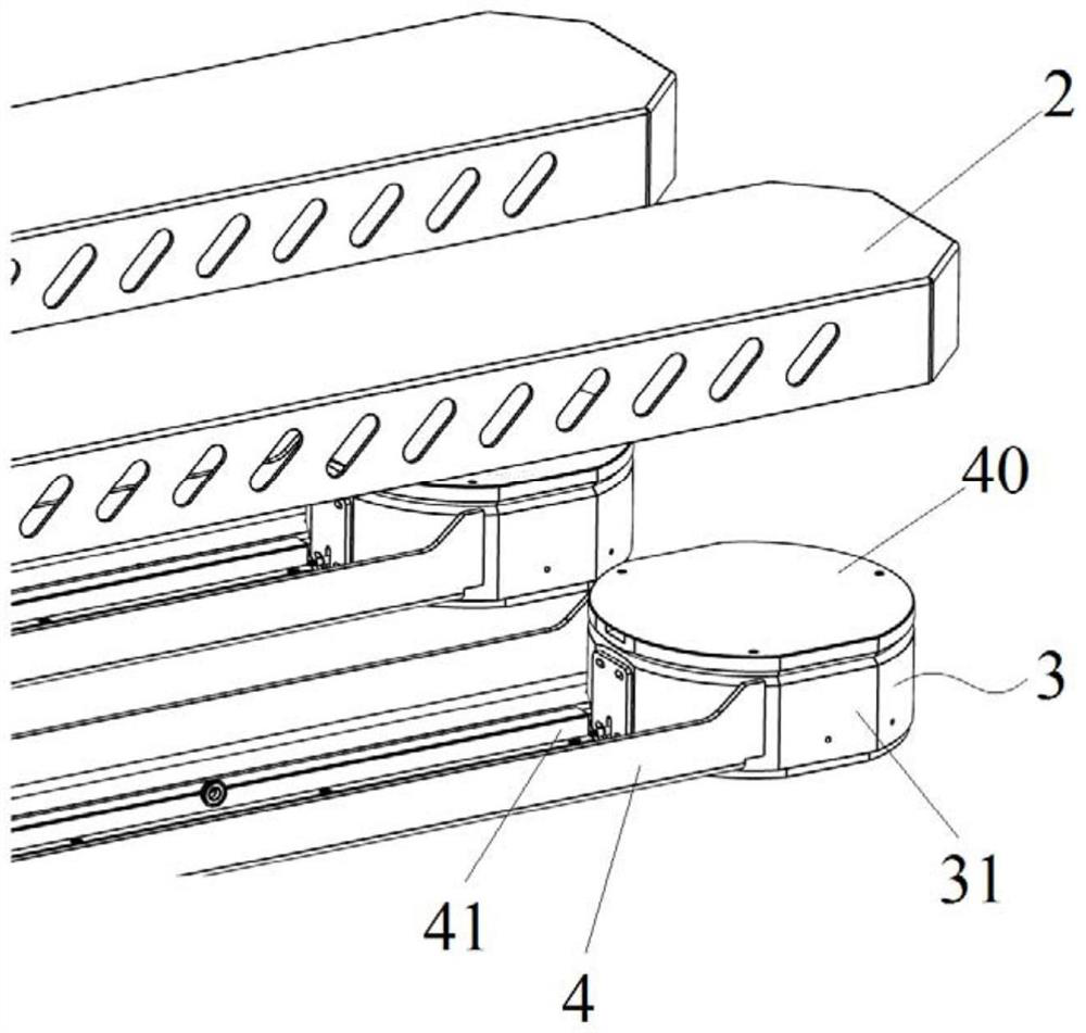
Double-wheel differential driving device and straddle type unmanned forklift

A differential drive, two-wheel technology, used in power units, electric power units, lifting devices, etc., can solve the problems of poor sideshift ability, inconsistent steering angle, low position and attitude adjustment accuracy, and improve control accuracy and stability. The effect of improved slack, sideshift and steering capabilities, and greater agility

Pending Publication Date: 2022-01-14
上海动亦科技有限公司
View PDF0 Cites 0 Cited by
  • Summary
  • Abstract
  • Description
  • Claims
  • Application Information

AI Technical Summary

Problems solved by technology

[0005] One is that the in-situ steering cannot be realized. The AGV equipment using this drive device cannot complete the angle adjustment in a small range in a limited space, resulting in poor lateral movement ability and low pose adjustment accuracy;
[0006] The second is that each driving wheel of the AGV car is driven independently, which requires relatively high control accuracy, otherwise the steering angle will be inconsistent, which will reduce the control accuracy and stability of the AGV car movement process

Method used


Image

  • Double-wheel differential driving device and straddle type unmanned forklift
  • Double-wheel differential driving device and straddle type unmanned forklift
  • Double-wheel differential driving device and straddle type unmanned forklift

Examples


Embodiment 1

[0048] Two-wheel route driver, such as Figure 4 and Figure 9 The differential drive unit including the mounting disk 31 and the mounting disk 31 is provided, and the mounting disk 31 is a cylindrical shape, and the top end is provided with a fixed disk 38, and an angle sensor 5 is provided on the differential drive unit, an electromagnetic push rod 9, a side roller. The 34 and top rollers 35, the side rollers 34 are rolled in contact with the mounting disk 31, and the top rollers 35 are rolled with the fixed disc 38, and the electromagnetic push rod 9 is set in the diameter direction of the mounting disk 31, such as Figure 10 The inner wall ring of the mounting disk 31 is provided with a plurality of locking sockets 311 that matches the electromagnetic push rod 9;

[0049] When the angle sensor 5 detects the steering angle of the differential drive unit, when the differential drive unit is rotated to a steering angle, the electromagnetic push rod 9 projects the push rod, insert th...

Embodiment 2

[0057] In the present embodiment, a two-wheel differential driving device further includes approaching switch 7, and a first mounting plate 39 is provided on the outer side wall of the mounting disk 31, and the proximity switch 7 is fixed to the first mounting plate 39, and along the mounting disk 31 The diameter direction passes through the sidewall wall of the mounting disk 31, and the initial sensing block 8 that matches the proximity switch 7 is provided on the differential drive unit;

[0058] The proximity switch 7 can sense the initial calibration of the steering angle of the two-wheel differential drive device to be initial induction block 8. Others are the same as in Example 1.

Embodiment 3

[0060] In this embodiment, a stopper 36 is provided on the differential driving unit, and the finish block 6 is provided on the fixed disk 38, and the height of the stopper 36 is matched, and the stopper 36 and the mounting disk 31 axis are between the barriers. The distance between the distance and the limit block 6 and the mounting disk 31 axis, the number of limit block 6 is two, and the two limit block 6 are set along the ring direction of the mounting disk 31, two limit block 6 The angle between the angle is 90 °, when the stopper 36 is blocked, the differential drive unit cannot continue to rotate, realize the limit on the maximum steering angle of the differential drive unit, the maximum steering angle is 270 °, avoid Wreathing the wire connected to the differential drive unit.

[0061] Others are the same as in Example 1.


PUM


Abstract

The invention relates to a double-wheel differential driving device. The device comprises a mounting disc (31) and a differential driving unit in the mounting disc (31), the mounting disc (31) is cylindrical, a fixing disc (38) is arranged at the top end of the mounting disc (31), and an angle sensor (5), electromagnetic push rods (9), a side roller (34) and a top roller (35) are arranged on the differential driving unit. The side roller (34) and the top roller (35) are in rolling contact with the mounting disc (31) and the fixing disc (38) respectively, the electromagnetic push rods (9) are arranged in the diameter direction of the mounting disc (31), and a plurality of locking insertion holes (311) matched with the electromagnetic push rods (9) are formed in the inner side wall of the mounting disc (31) in the circumferential direction at intervals. Compared with the prior art, the device has the advantages of high control precision, high flexibility, high reliability and the like.

Description

Technical field [0001] The present invention relates to the field of forklifts, in particular, to a two-wheel differential driving device and an inner legless unmanned forklift. Background technique [0002] AUTOMATED GUIDED VEHICLE, AGV), is often also referred to as an unmanned van, refers to an automatic guiding device equipped with electromagnetic or optical, can travel along a predetermined guide and various transfer functions. Transport vehicles, due to its characteristics of high automation, safety, flexibility, and is one of the best solutions to realizing material automatic transportation in China. [0003] Many production workshops or warehouses currently use AGV trolley to transport items to increase production or storage efficiency. The existing AGV trolley driver has two ways of steering wheel drive and differential drive. The rudder wheel can achieve a full-directional movement. Differential drives use two motors to drive two wheels, and achieve the steering of the ...

Claims


Application Information

Patent Timeline
Patent Type & Authority Applications(China)
IPC IPC(8): B66F9/075B60K1/02B62D11/04
CPCB66F9/07568B66F9/0755B66F9/07586B60K1/02B62D11/04
Inventor 郑培健朱明
Owner 上海动亦科技有限公司
Learn More