
Mechanical punching machine

A stamping machine and mechanical technology, applied in the direction of stamping machines, mechanical equipment, presses, etc., can solve the problems of high cost consumption, inability to apply pressure, and increase in the number of parts, and achieve the effect of reducing production costs and precise linear motion

Inactive Publication Date: 2014-01-29
周 桑完
View PDF8 Cites 0 Cited by
  • Summary
  • Abstract
  • Description
  • Claims
  • Application Information

AI Technical Summary

Problems solved by technology

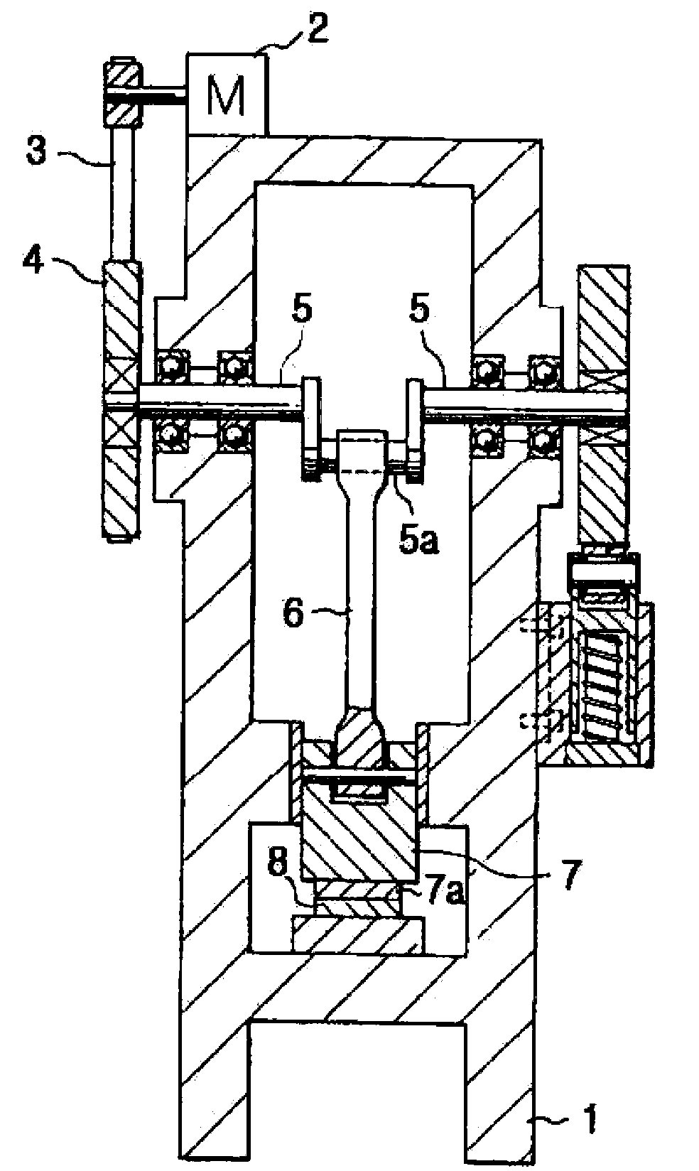
[0009] However, as mentioned above, the torque of the motor 2 passes through the crankshaft 4, and as the connecting rod 6 rotates up and moves, the slide rod 7 is reciprocated in the vertical direction, thereby applying pressure to the work object. The range of upward movement of the connecting rod 6 combined with the crank pin 5a connected to the crankshaft 5 cannot provide different pressures to various work objects, and the connecting rod 6 rotates and moves upward, so it cannot move to the exact position of the work object As a result, various defects in parts are caused, which brings a great burden on the production cost.
[0010] In addition, the mechanical punching machine is, although the ball screw method has the advantage of extending the range of linear motion to the desired range, but in order to prevent the rotation phenomenon of the pressure load accompanying the conversion of rotary motion into linear motion, necessary tools must be used. device, so there is a problem that the number of parts increases and the cost is high

Method used


Image

  • Mechanical punching machine
  • Mechanical punching machine
  • Mechanical punching machine

Examples


Embodiment 1

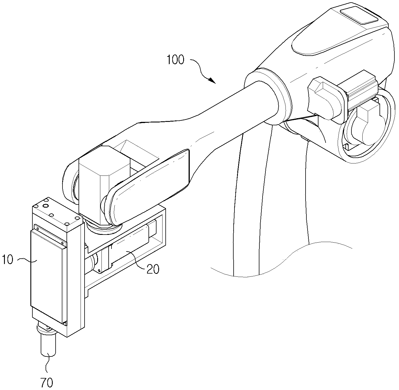
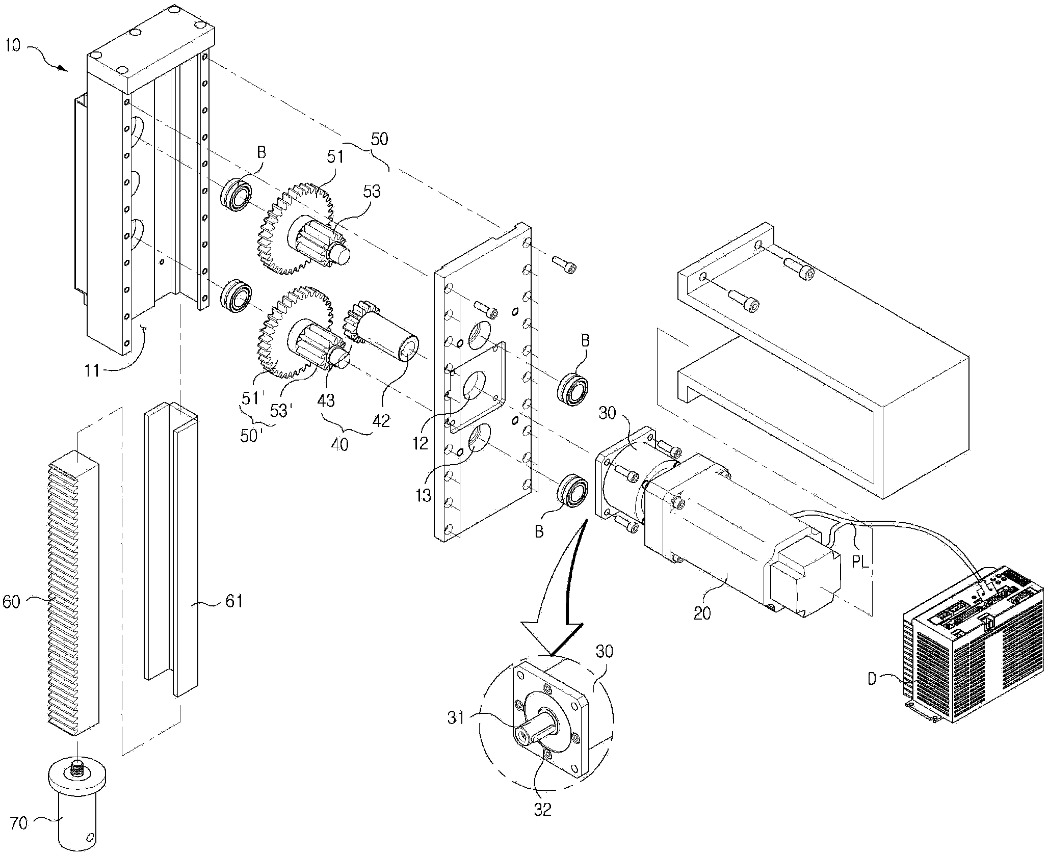
[0036] figure 2 is a schematic diagram of a mechanical punching machine according to the present invention; image 3 It is an exploded schematic view of the mechanical punching machine according to the first embodiment of the present invention; Figure 4a-Figure 4b for image 3 operating status diagram.

[0037] The invention provides a mechanical punching machine, which converts the rotary motion into a linear motion according to the transmission gear and the driving gear, and applies pressure to the object to be plastically deformed, so as to perform processing such as bending, shearing, and section shrinkage, or pressing Into the assembly of mechanical device parts.

[0038] The mechanical punching machine is composed of a hollow housing 10 with an opening 11 formed on one side and a through hole 12 formed on the side; a servo motor 20 disposed outside the housing 10; disposed between the servo motor 20 and the housing 10, The speed reducer 30 that decelerates the rota...

Embodiment 2

[0071] Figure 5 It is an exploded schematic view of the second embodiment of the mechanical punching machine according to the present invention; Figure 6a-Figure 6b for Figure 5 running status diagram; Figure 7 for Figure 5 Another state diagram of .

[0072] In the following description, the same symbols are used for the same structures as those of the first embodiment, and the description thereof is omitted.

[0073] The third gear 53, 53' of the power transmission gear part 50, 50' and the above-mentioned transmission gear 60 are also provided, arranged at predetermined intervals, and share the rotational power of the third gear 53, 53', and then transmit it to the above-mentioned transmission gear. A plurality of driving gears 80 of gear 60 .

[0074] In order to maximize the large-capacity torque transmission and the durability increase effect by the above-mentioned torque sharing, the above-mentioned transmission gear 60 further includes a transmission gear 60a...

Embodiment 3

[0083] Figure 8 It is a schematic diagram of the third embodiment of the mechanical punching machine according to the present invention; Figure 9 for Figure 8 Another state diagram for ; Figure 10 for Figure 9 Another state diagram for .

[0084] In the following description, the same symbols are used for the same structures as those of the first embodiment, and the description thereof is omitted.

[0085] The mechanical punching machine is composed of a hollow housing 10 with an opening 11 formed on one side and a through hole 12 formed on the side; a servo motor 20 disposed outside the housing 10; disposed between the servo motor 20 and the housing 10, The speed reducer 30 that decelerates the rotation speed of the above-mentioned servo motor 20; the power gear part 40 that is connected to the above-mentioned speed reducer 30 through the through hole 12 of the above-mentioned housing 10 to form a first gear 43; The transmission gear 60 of the gear 43; and the press...


PUM


Abstract

The invention provides a mechanical punching machine. The rotating speed of a servo motor of a speed reducer is converted to torque, a first gear of a power gear is rotated through the torque, a second gear, meshed with the first gear, of a power transmission gear part is rotated afterwards, and a third gear combined with a transmission gear in a meshed mode is rotated at the same time. The mechanical punching machine is composed of a small number of components, thereby ensuring that the transmission gear does precise linear motion and pressure loads of the transmission gear can be more precisely used for pressing work of the components of the mechanical punching machine and reducing manufacturing cost. The mechanical punching machine has the advantages that pressure provided for multiple kinds of action objects can differ even if rotating preventing means like a method using a ball screw are not needed to achieve precise linear motion so as to provide pressure for accurate positions of the action objects, the mechanical punching machine is composed of the small number of components, and production cost is reduced.

Description

technical field [0001] The present invention relates to a mechanical pressing machine (Mechanical Pressing Machine), especially relates to sharing the torque of the servo motor to multiple driving gears through the power transmission gear part formed by multiple gears, and transmitting it to the transmission gear at the same time, so that the torque of the servo motor can be compared with the pressure load. The integrated transmission gear converts the operation into accurate and precise linear motion, so it is a mechanical press machine that processes parts of mechanical devices or performs press-fit assembly work more precisely. Background technique [0002] In general, a press machine is a part that applies pressure to an object to be plastically deformed, thereby performing processing such as bending, shearing, and section shrinkage, or pressing into an assembly mechanism. According to different working objects or working methods, a variety of punching machines can be se...

Claims


Application Information

Patent Timeline
Patent Type & Authority Applications(China)
IPC IPC(8): B30B1/24F16H19/04
Inventor 周桑完
Owner 周 桑完
Learn More