Outer flanging crawler wheel

A track wheel and flanging technology, applied in the direction of wheels, transportation and packaging, vehicle parts, etc., can solve the problems of poor structural strength, track wheels can only be used as track wheels, etc., and achieve the effect of good strength

Active Publication Date: 2016-06-08
ZHEJIANG FENGCHI MECHANICAL
5 Cites 1 Cited by

AI-Extracted Technical Summary

Problems solved by technology

[0004] The first purpose of the present invention is to provide a track wheel with good structural strength and turned-out edge, which solves the problem of poor structural strength of the existing track wheels
[0005] The second object of the present invention aims at furt...

Abstract

The invention relates to crawler wheels and discloses an outer flanging crawler wheel. The outer flanging crawler wheel is characterized in that the crawler wheel comprises an outer-side half wheel and an inner-side half wheel; the outer-side half wheel is sequentially provided with an outer-side inner flanging, an outer-side crawler supporting ring and an outer-side half wheel arm from outside to inside; the outer-side half wheel arm is provided with an outer-side half central hole and outer-side half installation holes; the inner-side half wheel is sequentially provided with an inner-side inner flanging, an inner-side crawler supporting ring and an inner-side half wheel arm from inside to outside; the inner-side half wheel arm is provided with an inner-side half central hole and inner-side half installation holes; the outer-side half installation holes and the inner-side half installation holes are aligned to form installation holes; the outer-side half central hole and the inner-side half central hole are aligned to form a central hole; the outer-side half wheel arm and the inner-side half wheel arm are spliced and fixed together. The outer flanging crawler wheel provided by the invention is high in structural strength, and the problem that existing crawler wheels are poor in structural strength is solved.

Application Domain

Wheels

Technology Topic

FlangingEngineering

Image

  • Outer flanging crawler wheel
  • Outer flanging crawler wheel
  • Outer flanging crawler wheel

Examples

  • Experimental program(2)

Example Embodiment

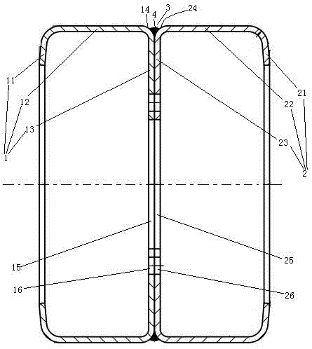
[0023] Embodiment one, see figure 1 , an outturned track wheel, comprising an outer half wheel 1 and an inner half wheel 2.
[0024] The outer half wheel 1 is provided with an outer inner flange 11, an outer track support ring 12 and Outer half spoke 13. The outer inner flange 11, the outer track support ring 12 and the outer half-spoke 13 are connected together in one structure. An outer chamfered surface 14 is provided between the outer track support ring 12 and the outer half-spoke 13 . The outer half spoke 13 is provided with an outer half central hole 15 and an outer half mounting hole 16 .
[0025] The inner half wheel 2 is provided with an inner inner flange 21 , an inner track support ring 22 and an inner half spoke 23 sequentially from the inner side to the outer side. The inner flange 21, the inner track support ring 22 and the inner half-spoke 23 are connected together in one structure. An inner chamfer surface 24 is provided between the inner track support ring 22 and the inner half spoke 23 . The inner half spoke 23 is provided with an inner half central hole 25 and an inner half mounting hole 26 . The outer half mounting hole 16 and the inner half mounting hole 26 are aligned to form a mounting hole. The outer half center hole 15 and the inner half center hole 25 are aligned to form a center hole. The outer half-spoke 13 and the inner half-spoke 23 are overlapped and fixed together. An annular groove 3 is formed between the outer chamfered surface 14 and the inner chamfered surface 24 . A weld seam 4 formed by welding is provided in the annular groove 3 . The weld seam 4 is an annular structure extending along the circumferential direction of the outer half wheel 1 . The outer half-spoke 13 and the inner half-spoke 23 are welded together by the weld seam 4 . The weld seam 4 is located in the annular groove 3 . The width of the weld 4 (that is, the dimension in the left-right direction in the figure) is 6-10 mm.
[0026] During use, crawler belt is installed on the outer side crawler support ring 12 and the inner side crawler support ring 22 simultaneously to realize the support to crawler belt, and car is walked by crawler belt support.

Example Embodiment

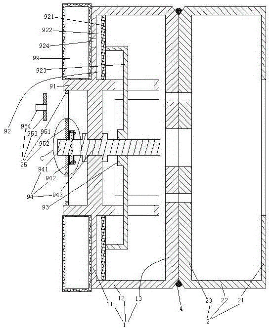
[0027] Embodiment two, the difference with embodiment one is:
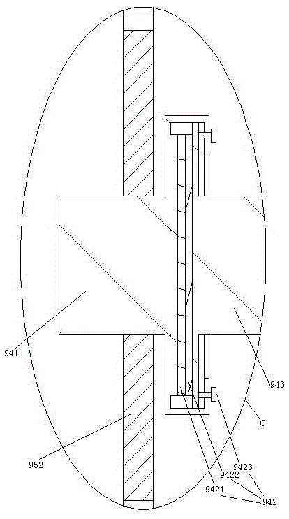
[0028] see figure 2, also includes a support mode switching mechanism 9. A tire support ring 91 is provided on the outer side of the outer inner flange 11 . The tire support ring 91 is coaxially fixed together with the outside half-wheel 1. The tire support ring 91 and the outer track support ring 12 are distributed along the axial direction of the outer half wheel 1 . A pneumatic tire 99 is provided on the tire support ring 91 . The support mode switching mechanism 9 includes an air storage cylinder 92 , a threaded sleeve 93 , a screw rod 94 and a differential mechanism 95 . The outer half wheel 1 is provided with an anti-rotation structure 911 . The anti-rotation structure 911 is an elongated hole disposed on the outer half wheel 91 and extending axially along the rim. The air storage cylinder 92 is arranged inside the outer inner flange 11 . The air storage cylinder 92 is an annular cylinder coaxial with the outer half-wheel 1 . An air charging piston 921 is arranged in the air storage cylinder 92 . The axis of the charging piston 921 is parallel to the axis of the outer half-wheel 1 . The charging piston 921 isolates the air storage cylinder 92 from the sealed cavity 922 . The sealed cavity 922 communicates with the tire 99 through the air channel 924 . The charging piston 921 is connected with the threaded sleeve 93 through at least two push rods 923 . The push rods 923 are distributed along the circumferential direction of the outer half wheel 1 . The push rods 923 pass through the elongated holes constituting the anti-rotation structure 911 one by one. The threaded mandrel 94 passes through the outer half wheel 1 . The screw rod 94 includes an input section 941 , a force limiter 942 and an output section 943 . One end of the output section 943 is rotationally connected with the outer half-wheel 1, and this end and the outer half-wheel 1 are also clamped together along the axial direction of the outer half-wheel 1, that is, the screw rod 94 cannot move. The other end of the output section 943 is connected with the output section 943 through the force limiter 942 . The threaded sleeve 94 is threaded on the output section 943 . The differential mechanism 95 includes an inner ring gear 951 , an outer ring gear 952 and a clutch gear 953 . The inner ring gear 951 is connected to the inner peripheral surface of the tire support ring 91 . The outer ring gear 952 is connected to the input section 941 . The outer ring gear 952 is located inside the inner ring gear 951, that is, the two are located on the same plane. The clutch gear 953 is provided with a connecting shaft 954 .
[0029] see image 3 , The force limiter 942 includes a first friction plate 9421 , a second friction plate 9422 and a locking force adjusting bolt 9423 . The first friction plate 9421 is connected to the input section 941 . The second friction plate 9422 is connected to the output section 943 . The first friction plate 9421 and the second friction plate 9422 are pressed together under the tightening action of the locking force adjusting bolt 9423 to transmit force through friction. It is also possible to adjust the friction between the first friction plate 9421 and the second friction plate 9422 by turning the locking force adjustment bolt 9423 to enable the magnitude of the transmission force.
[0030] see Figure 4 , the suspension of spoke is connected together with vehicle frame 98. When the inflation piston 921 is in this position, the pneumatic tire 99 is higher than the crawler belt (not shown in the figure), that is, the vehicle frame 98 is supported by the pneumatic tire 99 and walks.
[0031] When walking is supported by the track, the clutch gear 953 is inserted between the inner ring gear 951 and the outer ring gear 952 so that the inner ring gear 951 and the outer ring gear 952 are meshed together through the clutch gear 953 . Clutch gear 953 is also fixed together with vehicle frame 98 by connecting shaft 954 . Then make the wheel forward, under the effect of differential mechanism 95, the rotating speed of screw mandrel 94 is higher than the rotating speed of threaded sleeve 93, and threaded sleeve 93 also produces rightward translation with respect to screw mandrel 94, and the structure of translation is to drive charging piston 921 Moving to the right makes the gas in the pneumatic tire 99 flow into the sealed cavity 922 and makes the tire pressure not enough, so that it is enough to be flattened in the pneumatic tire to be supported by crawlers and realize walking.
[0032] When going to support walking by the pneumatic tire 99 again, the wheel is reversed. Translating, the gas in the sealing chamber 922 is pressed back in the pneumatic tire 99, so that the wheel is raised by the pneumatic tire 99 tire pressure and can not be flattened to be supported by the crawler belt, that is, supported and walked by the pneumatic tire. When the inflation piston 921 moves to the left to abut against the outer inner flange 11, the torque of the screw rod 94 will increase, causing the force limiter 942 to slip, thereby automatically realizing the rotation.
[0033] When it is not necessary to inflate and deflate, the clutch gear 953 is pulled out from between the first friction plate 9421 and the second friction plate 9422 .

PUM

PropertyMeasurementUnit
Width6.0 ~ 10.0mm

Description & Claims & Application Information

We can also present the details of the Description, Claims and Application information to help users get a comprehensive understanding of the technical details of the patent, such as background art, summary of invention, brief description of drawings, description of embodiments, and other original content. On the other hand, users can also determine the specific scope of protection of the technology through the list of claims; as well as understand the changes in the life cycle of the technology with the presentation of the patent timeline. Login to view more.

Similar technology patents

Artificial quartz sheet material and preparation method thereof

Owner:FOSHAN GAOMING DISTRICT MINGCHENG TOWN NEW ENERGYNEW MATERIAL IND TECH INNOVATION CENT

Composite catalyst and preparation method therefor

ActiveUS20160367972A1good strengthhigh activity
Owner:CHINA PETROCHEMICAL CORP +1

Ambroid handiwork and manufacturing method thereof

InactiveCN101973179Agood strengthhigh transparency
Owner:CHANGSHU HENGSHENG ARTS & CRAFTS

Epoxy molding compound filled with high amount of silica powder and preparation method thereof

ActiveCN103665775Agood strengthLow thermal elastic modulus
Owner:WUXI CHUANGDA ELECTRONICS

Classification and recommendation of technical efficacy words

  • good strength

Austenitic stainless steel medium-thick plate and manufacture method thereof

ActiveCN101724789Agood strengthGood corrosion resistance and ductility
Owner:BAOSTEEL DESHENG STAINLESS STEEL

Fiber-woven pultrusion pipeline and production method

ActiveCN102777708AHigh strength and stiffness and impact resistancegood strength
Owner:深圳鑫宝通材料科技有限公司
Why Eureka
Try Eureka