Unmanned aerial vehicle landing method based on optical flow method and horizon line detection

A UAV, horizon technology, applied in aircraft landers, unmanned aerial vehicles, motor vehicles, etc., can solve the problems of inability to obtain UAV attitude information, detection errors, etc., to reduce the amount of calculation and increase the accuracy rate , the effect of improving the accuracy

Active Publication Date: 2016-06-08
HARBIN INST OF TECH
View PDF5 Cites 21 Cited by
  • Summary
  • Abstract
  • Description
  • Claims
  • Application Information

AI Technical Summary

Problems solved by technology

However, only using the horizon position information cannot obtain very accurate attitude information of the UAV. At the same time, there will be problems such as detection errors when extracting the horizon line information. A common interference is the runway

Method used


Image

  • Unmanned aerial vehicle landing method based on optical flow method and horizon line detection
  • Unmanned aerial vehicle landing method based on optical flow method and horizon line detection
  • Unmanned aerial vehicle landing method based on optical flow method and horizon line detection

Examples


specific Embodiment approach 1

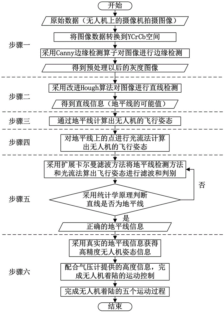
[0078] Specific Embodiment 1: This embodiment provides a UAV landing method based on the optical flow method and horizon detection. The horizon is detected by using the straight line detection method for the image, and the roll in the flight attitude of the UAV is calculated according to the horizon. Rotation angle and azimuth angle; use the optical flow method to calculate the pose of the UAV for the horizon in the sequence images taken during the flight of the UAV; use the extended Kalman filter method to reduce the detection error rate of the horizon in the method, and by the position It can switch between the five stages of UAV landing, and cooperate with the horizon method to complete the autonomous landing process of UAV landing one by one.

[0079] like figure 1 As shown, it is divided into five steps, and the specific steps are as follows:

[0080] Step 1: Perform image preprocessing on the video captured by the camera fixed at the bottom of the drone during the flig...


PUM


Abstract

The invention discloses an unmanned aerial vehicle landing method based on an optical flow method and horizon line detection. The unmanned aerial vehicle landing method includes the steps that (1) video images shot by a camera fixed to the bottom of an unmanned aerial vehicle in the flying process are subjected to image preprocessing; (2) each image is subjected to line detection, and horizon line information in the images is obtained; (3) the horizon line information is calculated, so that the current flying attitudes of the unmanned aerial vehicle are obtained; (4) attitude information of the unmanned aerial vehicle is detected out through the optical flow method; (5) in combination with a motion model of the unmanned aerial vehicle, the unmanned aerial vehicle attitudes obtained through the optical flow method and horizon line detection are filtered through an extended Kalman filter method, and correct horizon line information is sorted out; and (6) the autonomous landing process based on the unmanned aerial vehicle is achieved. The unmanned aerial vehicle landing method is used for the situation of detecting a fixed target through a dynamic object in the flying process, and the optical flow method based on gradient is used so as to well cooperate with movement of a detector. Compared with traditional visual algorithms based on horizon line detection, the unmanned aerial vehicle landing method based on the optical flow method and horizon line detection can effectively improve accuracy in the landing process and is applicable to autonomous landing of the unmanned aerial vehicle.

Description

technical field [0001] The invention relates to a landing method of an unmanned aerial vehicle, in particular to an image processing method based on horizon detection and optical flow velocity measurement, which is used in the landing process of the unmanned aerial vehicle. Background technique [0002] UAV is short for "unmanned aerial vehicle" (UAV). In 1917, the United Kingdom developed the first unmanned aerial vehicle, which was used as a "target drone". It was in the 1960s and 1970s that it was really used as a flying weapon for actual combat. From the 1980s. The importance of UAVs in various countries has promoted the development and use of UAVs. Nowadays, the development momentum of UAVs is becoming stronger and stronger, and the research on UAV reconnaissance aircraft is becoming more mature. [0003] Due to its many advantages, such as good concealment, strong vitality, low cost, no fear of casualties, simple take-off and landing, and flexible movements, drones h...

Claims


Application Information

Patent Timeline
Patent Type & Authority Applications(China)
IPC IPC(8): B64C39/02B64D45/04
CPCB64C39/02B64D45/04B64U70/00
Inventor 张淼郑菱莎沈毅
Owner HARBIN INST OF TECH
Why Eureka
Try Eureka