
Sewage barrier-free lifting water distribution system

A technology for water distribution system and sewage, applied in waterway system, sewer system, water supply device, etc., can solve the problems of sewage lifting and water distribution structure with many accessories, high engineering cost and large area.

Inactive Publication Date: 2017-08-11
CHANGYI HAIYANG WATER IND
View PDF11 Cites 0 Cited by
  • Summary
  • Abstract
  • Description
  • Claims
  • Application Information

AI Technical Summary

Problems solved by technology

[0002] In the process of sewage treatment, it is often necessary to transport the sewage under treatment from the previous treatment process to the next treatment process. For example, the sewage is lifted from the low water level process to the high water level process. The current sewage transportation mostly uses special pumps There are several lifting pumps installed in the pump room, and there is a valve well next to the pump room. Each lifting pump is equipped with an expansion joint, a control valve and a valve combination of two one-way valves in the valve well. It is necessary to manipulate the control valve and two one-way valves to prevent the sewage from flowing backwards before repairing. In this way, multiple sets of lifting pumps have multiple sets of the same valve combination, and then they are connected in parallel. After that, the sewage is lifted and collected for water distribution, so that the sewage is lifted and distributed. There are many structural parts, high cost of parts, many failure points, and there will be many maintenance points and repair parts during operation in the future, which is not conducive to operation management, and special valve wells need to be set up, occupying a large area, and the project cost is high

Method used


Image

  • Sewage barrier-free lifting water distribution system
  • Sewage barrier-free lifting water distribution system
  • Sewage barrier-free lifting water distribution system

Examples


Embodiment Construction

[0019] Below in conjunction with accompanying drawing and embodiment, further elaborate the present invention. In the following detailed description, certain exemplary embodiments of the invention are described by way of illustration only. Needless to say, those skilled in the art would realize that the described embodiments can be modified in various different ways, all without departing from the spirit and scope of the present invention. Accordingly, the drawings and description are illustrative in nature and not intended to limit the scope of the claims.

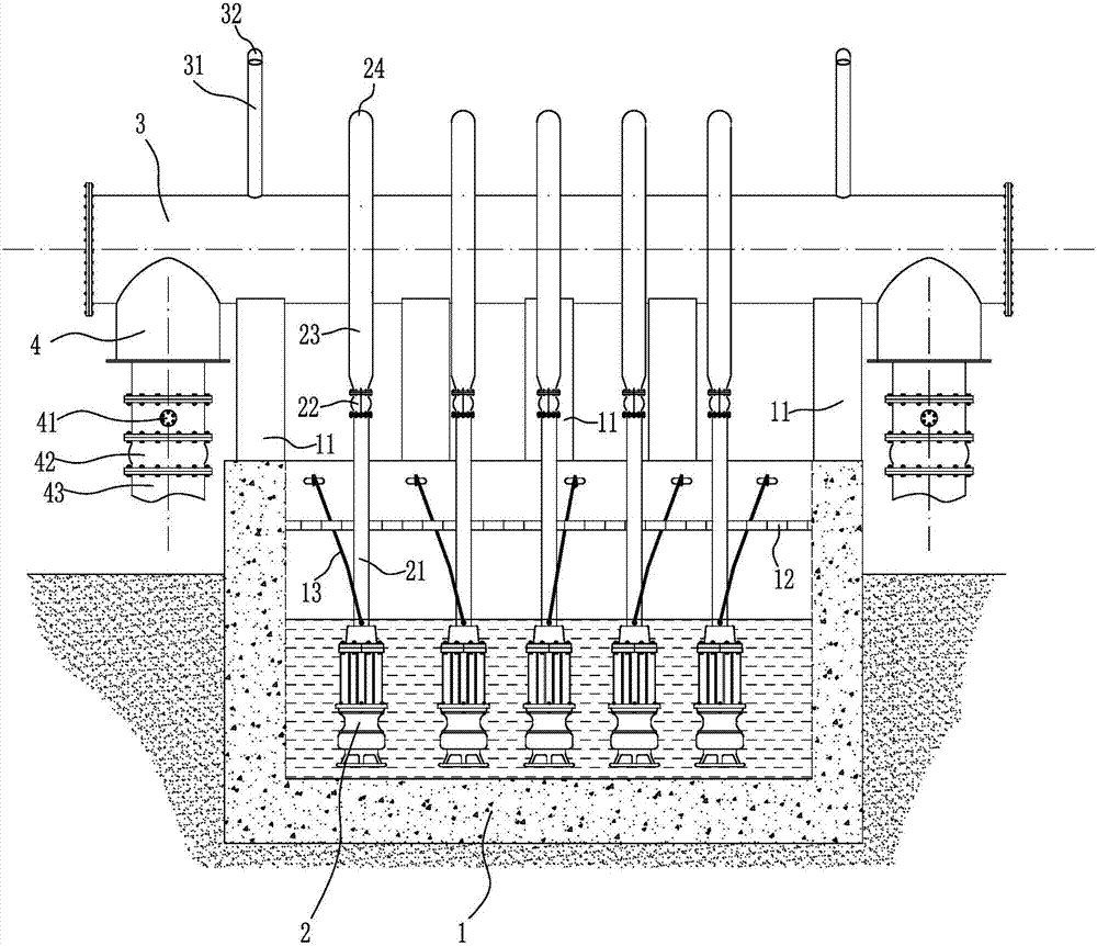
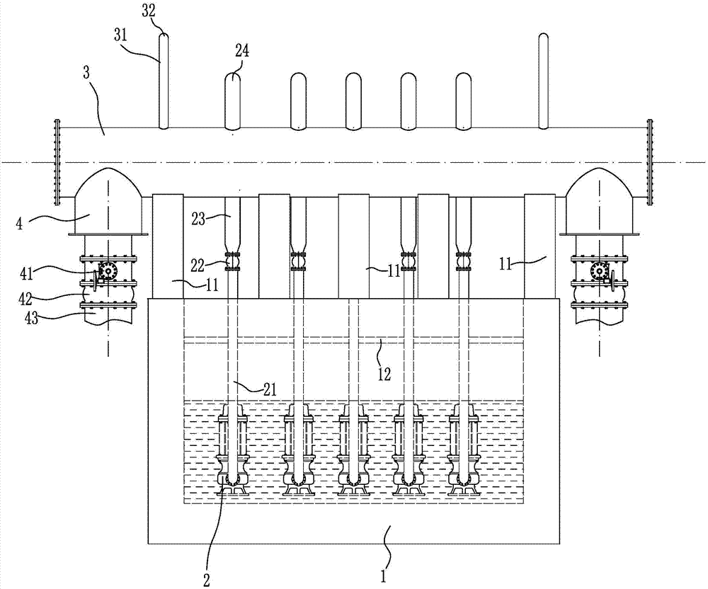
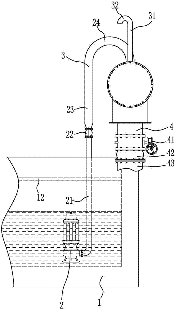
[0020] Such as figure 1 , figure 2 and image 3 As shown, the sewage barrier-free lifting water distribution system includes a number of lifting pumps 2 arranged in the sewage pool 1, and an isolation net 12 is arranged above the lifting pump 2 in the sewage pool 1. There is a closed wading pipe body 3, and the water outlet end of the lift pump 2 is connected with a water outlet pipe 21, and the water outlet pipe 21 ...


PUM


Abstract

The invention discloses a sewage non-fault lifting water distribution system which comprises a plurality of lifting pumps arranged in a sewage pool. A separation net is arranged in the sewage pool and above the lifting pumps; a closed water passing tube body is arranged above the sewage pool; the water outlet ends of the lifting pumps are connected with water outlet pipes; the water outlet pipes pass through the separation net and are connected with compensation devices in a detachable manner; the compensation devices are connected with water inlet pipes; the upper ends of the water inlet pipes are higher than the water passing tube body; bent tube parts which are bent downwards to be connected with the top of the water passing tube body are arranged at the upper ends of the water inlet pipes; a gas communication device is arranged at the top of the water passing tube body; and a water distribution device is arranged at the bottom of the water passing tube body. The sewage non-fault lifting water distribution system occupies a small area, is low in construction cost, uses a small quantity of accessories, is low in accessory cost, has a small number of fault generation points, has a small number of repair points in the operation process, and is beneficial to operation management.

Description

technical field [0001] The invention relates to sewage treatment equipment, in particular to a sewage barrier-free lifting water distribution system. Background technique [0002] In the process of sewage treatment, it is often necessary to transport the sewage under treatment from the previous treatment process to the next treatment process. For example, the sewage is lifted from the low water level process to the high water level process. The current sewage transportation mostly uses special pumps There are several lifting pumps installed in the pump room, and there is a valve well next to the pump room. Each lifting pump is equipped with an expansion joint, a control valve and a valve combination of two one-way valves in the valve well. It is necessary to manipulate the control valve and two one-way valves to prevent the sewage from flowing backwards before repairing. In this way, multiple sets of lifting pumps have multiple sets of the same valve combination, and then th...

Claims


Application Information

Patent Timeline
Patent Type & Authority Patents(China)
IPC IPC(8): E03F5/22E03F3/02E03F3/04
CPCE03F3/02E03F3/04E03F5/22
Inventor 于富友孙绪强李培明
Owner CHANGYI HAIYANG WATER IND
Learn More