Cosmetic processing and stirring equipment based on bubble-overflowing prevention technology

A technology for mixing equipment and cosmetics, applied in mixer accessories, mixers with rotating mixing devices, chemical instruments and methods, etc., can solve problems such as punching equipment and material waste, achieve accuracy, improve mixing quality, Ensure the effect of stirring and mixing quality

Inactive Publication Date: 2021-03-12
崔星海
View PDF0 Cites 0 Cited by
  • Summary
  • Abstract
  • Description
  • Claims
  • Application Information

AI Technical Summary

Problems solved by technology

However, the existing cosmetics processing and stirring equipment is easy to rush out of the equipment due to foaming when feeding, which leads to waste of materials

Method used


Image

  • Cosmetic processing and stirring equipment based on bubble-overflowing prevention technology
  • Cosmetic processing and stirring equipment based on bubble-overflowing prevention technology
  • Cosmetic processing and stirring equipment based on bubble-overflowing prevention technology

Examples


Embodiment 1

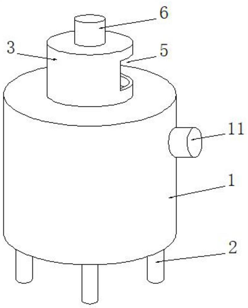
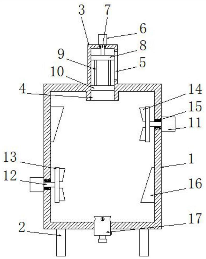
[0029] See Figure 1-2 , a cosmetics processing and stirring equipment based on foaming and overflow prevention technology, comprising a kettle body 1, the bottom of the kettle body 1 is evenly provided with a number of legs 2, and the top of the kettle body 1 is connected to the feeding cylinder 3 through, so The bottom end of the feeding tube 3 is connected to the sealing sleeve 4, and the feeding tube 3 is connected to the kettle body 1 through the sealing sleeve 4. The axis of the feeding tube 3 is overlapped with the axis of the sealing sleeve 4 and the axis of the kettle body 1. One side end of tube 3 connects feeding hole 5 through, and the top of charging tube 3 is fixedly connected with electric telescopic device 6, and the bottom end of telescopic rod 7 on described electric telescopic device 6 is connected with charging tube 3 top wall and is fixedly connected with The upper sealing plate 8 matched with the feeding cylinder 3 is slidingly connected between the teles...

Embodiment 2

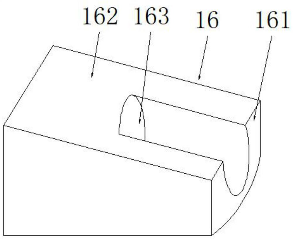
[0033] See Figure 3-4 , the difference from Embodiment 1 is: the deflector assembly 16 includes a plate body 161, the plate body 161 is fixedly connected to the inner cavity wall of the kettle body 1, and the plate body 161 is horizontally connected to the stirring assembly Correspondingly, the side end surface of the plate body 161 is provided with a drainage surface 162, and the drainage surface 162 is arranged obliquely, and the auxiliary pushing hole 163 matched with the drainage surface 162 is provided in the described plate body 161, and the auxiliary pushing hole 163 is provided with An auxiliary push fan 164 is provided, and the auxiliary push fan 164 is fixedly connected to the inner cavity wall of the auxiliary push hole 163 through a fixed rod 165, and the raw material in the kettle body 1 is stirred by the stirring assembly, so that the raw material rushes to the drainage surface 62 and the auxiliary push hole 163. Push the hole 163, and at the same time further p...

Embodiment 3

[0036] See Figure 5-6 , the difference from Example 1 is: the discharge cylinder 17 includes a cylinder 171, the cylinder 171 is a cylindrical structure with an open bottom, and the cylinder 171 is embedded on the bottom wall of the kettle body 1 , the outer circular surface of the cylinder 171 is evenly provided with a number of through holes 172, the through holes 172 are provided with a control valve 173, one side of the cylinder 171 is embedded with a control switch 170, the control switch 170 It is electrically connected with the control valve 173, the bottom end of the cylinder 171 is open and internally threaded to the sealing cover 174, the top of the sealing cover 174 is provided with a diversion hole 175, and the bottom end of the diversion hole 175 The discharge pipe 176 is connected through, the bottom end of the discharge pipe 176 is covered with a sealing plug 177, a number of support rods 178 are evenly arranged in the guide hole 175, and the top ends of all th...


PUM


Abstract

The invention discloses a cosmetic processing and stirring equipment based on bubble-overflowing prevention technology. The cosmetic processing stirring equipment comprises a kettle body, the top endof the kettle body is connected with a feeding cylinder in a penetrating mode, the bottom end of the feeding cylinder is connected with a sealing sleeve in a penetrating mode, the feeding cylinder isconnected with the kettle body through the sealing sleeve in a penetrating mode, and the top end of the feeding cylinder is fixedly connected with an electric telescopic device. The bottom end of a telescopic rod on the electric telescopic device is connected with the top wall of the feeding cylinder in a penetrating mode and fixedly connected with an upper sealing plate matched with the feeding cylinder, a plurality of connecting rods are evenly arranged at the bottom end of the upper sealing plate, and the bottom ends of all the connecting rods are jointly and fixedly connected with a lowersealing plate. By means of the equipment, raw materials are added above the lower sealing plate through the feeding hole, then the telescopic rod extends out through the electric telescopic device, the lower sealing plate is descended through the telescopic rod, then the raw materials above the lower sealing plate are conveyed to an inner cavity of the kettle body, and the upper sealing plate descends under the action of the telescopic rod and is matched with the sealing sleeve to seal the feeding cylinder; therefore, bubble-overflowing caused by the addition of the raw materials in the kettlebody can be effectively prevented.

Description

technical field [0001] The invention relates to the technical field of cosmetic stirring equipment, in particular to a cosmetic processing stirring equipment based on foam overflow prevention technology. Background technique [0002] Cosmetics refer to smearing, spraying or other similar methods that are spread on any part of the human body surface, such as skin, hair, nails, lips and teeth, etc., to achieve cleaning, maintenance, beauty, modification and change of appearance, or to correct human body odor, maintain Chemical industrial products or fine chemical products for the purpose of good condition. [0003] During the processing of cosmetics, mixing equipment is needed to mix various raw materials to promote production. However, the existing cosmetic processing and stirring equipment is easy to rush out of the equipment due to foaming during feeding, which leads to waste of materials. For this reason, the present invention discloses a cosmetics processing and stirrin...

Claims


Application Information

Patent Timeline
Patent Type & Authority Applications(China)
IPC IPC(8): B01F7/04B01F15/00B01F15/02
CPCB01F27/706B01F35/5311B01F35/187B01F35/7547B01F2101/21
Inventor 崔星海
Owner 崔星海
Why Eureka
Try Eureka