Al technical title is built by PatSnap Al team. It summarizes the technical point description of the patent document.
A fan speed and control device technology, applied in pump control, engine control, non-variable pumps, etc., can solve problems such as increased thermal power, fan failure, and increased thermal power of equipment, so as to avoid increased noise and realize control Effect
Active Publication Date: 2016-06-08
QINGDAO HISENSE LASER DISPLAY CO LTD
View PDF10 Cites 25 Cited by
Summary
Abstract
Description
Claims
Application Information
AI Technical Summary
This helps you quickly interpret patents by identifying the three key elements:
Problems solved by technology
Method used
Benefits of technology
Problems solved by technology
But once the speed of the fan exceeds the rated value of the speed, the fan itself will generate heat when it is overloaded for a long time, and the longer the time, the greater the heat generated. On the contrary, it may increase the thermal power of the equipment; in addition, the higher the fan speed and the greater the air volume, the greater the noise will be, and the fan may produce strong noise during long-term high-speed operation; and because the fan is Mechanical components, long-term high-speed operation may shorten the life of the fan and cause early failure of the fan
[0004] However, in the prior art, for some equipment with large heat generation, in order to ensure that the temperature of the equipment will not exceed the upper limit, the fan is usually fixed at a relatively high speed to ensure that the temperature of the entire equipment system does not exceed the upper limit, although it is always at Relatively high heat dissipation efficiency, but the noise is often increased, and the thermal power will also increase, and it is easy to cause early failure of the fan
Method used
Image
Click on the blue label to locate the original text in one second.
Reading with bidirectional positioning of images and text.
Examples
Embodiment Construction
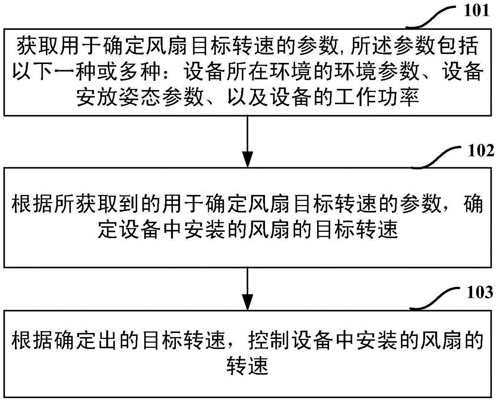
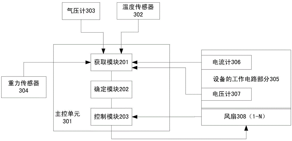
[0054] In order to make the object, technical solution and advantages of the present invention clearer, the present invention will be further described in detail below in conjunction with the accompanying drawings. Obviously, the described embodiments are only some embodiments of the present invention, rather than all embodiments . Based on the embodiments of the present invention, all other embodiments obtained by persons of ordinary skill in the art without making creative efforts belong to the protection scope of the present invention.
[0055] The fan installed in the device is used as a heat dissipation tool. As the application situation and the ambient temperature change, fans with different speeds will be required to meet the demand. Although there are some fans that can adjust the fan speed in the prior art, they are often based on the heat dissipation of the equipment or the heat dissipation efficiency of the equipment. Fixing the fan at a relatively high rotational ...
PUM
Abstract
The invention discloses a fan rotation speed control method and device. The method is applied to equipment provided with a fan. The method includes the steps that parameters for determining the target rotation speed of the fan are obtained, and the parameters comprise one or more of the environment parameter of the environment where the equipment is located, the equipment arrangement posture parameter and the work power of the equipment; the target rotation speed of the fan installed in the equipment is determined according to the obtained parameters for determining the target rotation speed of the fan; the rotation speed of the fan installed in the equipment is controlled according to the determined target rotation speed. By means of the fan rotation speed control method and device, the rotation speed of the fan can be controlled accurately.
Description
technical field [0001] The invention relates to the technical field of heat dissipation, in particular to a fan speed control method and a fan speed control device. Background technique [0002] As a common heat dissipation tool, fans are widely used in computers, communication products, optoelectronic products, consumer electronics, automotive electronic equipment, switches, medical equipment, heaters, air conditioners, frequency converters, teller machines, car freezers, welding Machines, induction cookers, audio equipment, environmental protection equipment, refrigeration equipment and other traditional or modern equipment. [0003] Usually within a certain speed range, the higher the speed of the fan, the better the cooling effect it can achieve. But once the speed of the fan exceeds the rated value of the speed, the fan itself will generate heat when it is overloaded for a long time, and the longer the time, the greater the heat generated. On the contrary, it may incr...
Claims
Application Information
Patent Timeline
Application Date:The date an application was filed.
Publication Date:The date a patent or application was officially published.
First Publication Date:The earliest publication date of a patent with the same application number.
Issue Date:Publication date of the patent grant document.
PCT Entry Date:The Entry date of PCT National Phase.
Estimated Expiry Date:The statutory expiry date of a patent right according to the Patent Law, and it is the longest term of protection that the patent right can achieve without the termination of the patent right due to other reasons(Term extension factor has been taken into account ).
Invalid Date:Actual expiry date is based on effective date or publication date of legal transaction data of invalid patent.