A Method for Eliminating Thermal Deviation of Working Fluid in External Heat Exchanger
A heat exchanger, external technology, applied in the direction of combustion method, lighting and heating equipment, fuel burning in melting state, etc., can solve the thermal deviation of working medium, the difference of heat transfer effect, and the efficiency of circulating fluidized bed boiler unit Difficult to realize and other problems, to achieve the effect of eliminating thermal deviation of working fluid and improving fluidization effect
- Summary
- Abstract
- Description
- Claims
- Application Information
AI Technical Summary
Problems solved by technology
Method used
Image
Examples
Embodiment 1
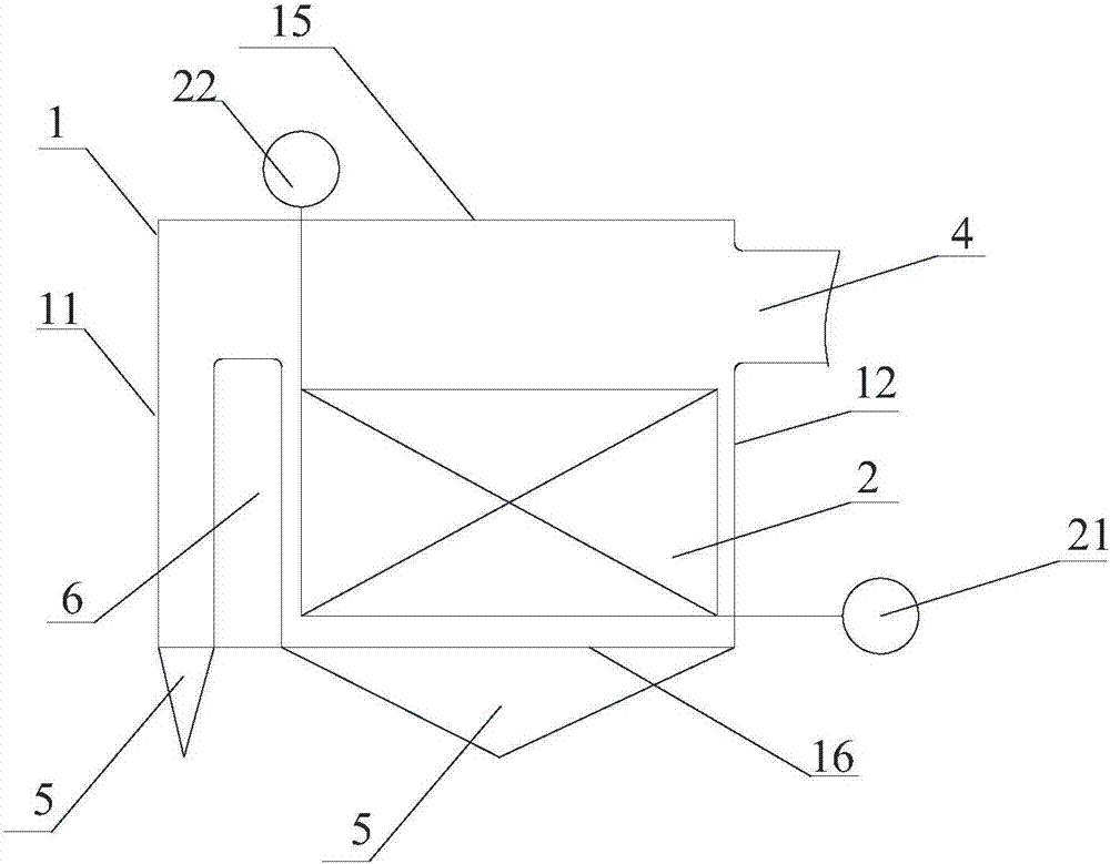
[0033] Such as image 3 , Figure 4 , Figure 5 As shown, an external heat exchanger for a 660MW ultra-supercritical circulating fluidized bed boiler includes a shell 1, a partition wall 6, a heating surface tube panel 2, an inlet header 21, an outlet header 22, an inlet ash Road 3, outlet gray road 4, air chamber 5, wind cap; shell 1 includes front wall 11 and rear wall 12, first side wall 13 and second side wall 14, top plate 15 and bottom air distribution plate along the particle flow direction 16. The width of the top plate is L1, and the width of the bottom air distribution plate 16 is L, wherein L is designed according to the specific standard of the heat exchanger; the inlet header 21 and the outlet ash channel 4 are located on the rear wall 12 of the shell 1 , the outlet header 22 is located on the top plate 15 of the housing 1, the inlet ash channel 3 is located on the second side wall 14 of the housing 1, and the air chamber 5 is located under the air distribution ...
Embodiment 2
[0037] Such as Figure 6 , Figure 7 As shown, an external heat exchanger for a circulating fluidized bed boiler with a parameter of 700°C, including a shell 1, a partition wall 6, a tube panel 2 on a heating surface, an inlet header 21, an outlet header 22, and an inlet gray passage 3. Exit ash channel 4, air chamber 5, air cap; shell 1 includes front wall 11 and rear wall 12, first side wall 13 and second side wall 14, top plate 15 and bottom air distribution plate 16 along the particle flow direction , the width of the top plate is L1, the width of the bottom air distribution plate 16 is L, the inlet header 21 and the outlet ash channel 4 are located on the rear wall 12 of the shell 1, and the outlet header 22 is located on the top plate of the shell 1 15, the inlet gray passage 3 is located on the second side wall 14 of the housing 1, and the air chamber 5 is located under the air distribution plate 16 on the bottom surface of the housing 1; Divided into three compartmen...
Embodiment 3
[0041] Such as Figure 8 As shown, the difference between this embodiment and the second embodiment is that the angle β between the two side walls and the extension surface of the bottom air distribution plate 16 is 45°, so that the heating surface can be arranged in a wider space, and the external type The ratio of the width B of the gray channel 4 at the outlet of the heat exchanger to the width L1 of the top plate 15 is 0.6, so that the width can fully cover the width of the tube panel on the heating surface of the external heat exchanger, thereby achieving the purpose of reducing the thermal deviation of the working medium.
PUM
 Abstract
Description
Claims
Application Information
 - R&D
- Intellectual Property
- Life Sciences
- Materials
- Tech Scout
- Unparalleled Data Quality
- Higher Quality Content
- 60% Fewer Hallucinations
Browse by: Latest US Patents, China's latest patents, Technical Efficacy Thesaurus, Application Domain, Technology Topic, Popular Technical Reports.
© 2025 PatSnap. All rights reserved.Legal|Privacy policy|Modern Slavery Act Transparency Statement|Sitemap|About US| Contact US: help@patsnap.com


