
A real-time damage monitoring system for truss structures with high damage sensitivity

A high-damage-sensitivity, real-time monitoring system technology, applied in the direction of machine/structural component testing, measuring devices, instruments, etc., can solve the problems of damage location accuracy, influence, and restrictive use, and achieve high accuracy and high application Value, energy saving effect

Active Publication Date: 2018-04-24
DALIAN UNIV OF TECH
View PDF4 Cites 0 Cited by
  • Summary
  • Abstract
  • Description
  • Claims
  • Application Information

AI Technical Summary

Problems solved by technology

However, the application of this method to engineering structures faces two difficulties: first, the method requires parameter identification to build a flexibility matrix, and test noise has a great impact on the quality of parameter identification, especially the identification of mode shapes, which in turn affects the quality of the method. Second, the sensitivity of this method to small damage needs to be further improved. The damage sensitivity of this method to different types of truss rods is different, and the damage to the oblique rod in the vertical plane of the truss is the most sensitive, but it can only identify The damage can only be successfully identified when the stiffness of the truss diagonals drops by about 25%, and the stiffness of the vertical bars of the trusses drops by about 70%.
These two points greatly restrict the application of this method in actual engineering

Method used


Image

  • A real-time damage monitoring system for truss structures with high damage sensitivity
  • A real-time damage monitoring system for truss structures with high damage sensitivity
  • A real-time damage monitoring system for truss structures with high damage sensitivity

Examples


Embodiment Construction

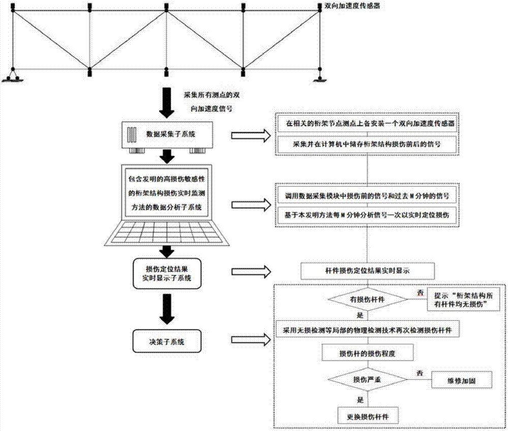
[0032] A numerical model of a simply supported truss structure is taken as an example to verify the effectiveness of the damage real-time monitoring method in the present invention. The truss structure real-time monitoring method with high damage sensitivity proposed by the present invention is specifically described below in conjunction with the accompanying drawings:

[0033] 1) Establish a numerical model of the truss structure

[0034] like figure 2 , the span of the truss structure model is 5.6m, a total of 14 rooms each with a length of 0.4m; the truss structure has 56 truss nodes and 160 truss rods; the boundary conditions at both ends of the truss structure are set to be hinged at one end and sliding at one end .

[0035] 2) Measuring point layout and damage conditions

[0036] like image 3 As shown in , the truss substructure in the dotted box is selected as the research object for truss bar damage location. As shown in Table 1, 8 damage conditions are set to i...


PUM


Abstract

The invention provides a high-damage-sensitivity truss structure damage real-time monitoring system, and belongs to the field of structure health monitoring. The system comprises a bidirectional acceleration sensor subsystem, a data collection subsystem, a data analysis subsystem, a damage positioning result real-time display subsystem and a decision making subsystem. The data analysis subsystem calls a bidirectional acceleration signal of the data collection subsystem and conducts damage recognition on the basis of the method. If a damaged rod exists, the damage degree of the damaged rod is detected through the non-destructive detection technology, and then a replacement or maintenance decision is made. The system has the outstanding advantages that high sensitivity to truss rod tiny damage, namely, rigidity reduction of 5% or below is achieved, and the damage rod can be found earlier at the initial stage of damage. No system identification or matrix operation processes are needed, the calculation speed is high, precision is high, the electric consumption is lowered when wireless sensors are used, and because of the ultrahigh sensitivity to small damage, high application value is achieved in practical projects.

Description

technical field [0001] The invention belongs to the technical field of structural health monitoring based on vibration information, relates to real-time damage monitoring of truss structures, and in particular invents a real-time monitoring system for locating tiny damaged truss rods. Background technique [0002] At present, there are a variety of damage monitoring methods for truss structures based on vibration information; the most widely used method is the stochastic damage location vector (SDLV) method proposed by Professor Bernal of Northeastern University, which is suitable for real-time damage location under environmental excitation. Experimental verification by Professor Spencer and others at the University of Illinois at Urbana-Champaign. However, the application of this method to engineering structures faces two difficulties: first, the method requires parameter identification to build a flexibility matrix, and test noise has a great impact on the quality of param...

Claims


Application Information

Patent Timeline
Patent Type & Authority Patents(China)
IPC IPC(8): G01M99/00
CPCG01M99/004
Inventor 安永辉布莱秋斯基·巴特楼密尔欧进萍
Owner DALIAN UNIV OF TECH
Learn More