
Surface frame installation structure of liquid crystal display device and liquid crystal display device

A technology of liquid crystal display and installation structure, which is applied in the direction of instruments, nonlinear optics, optics, etc. It can solve the problem that the surface frame installation structure cannot take into account the ultra-narrow effect and the appearance effect, so as to solve the bad aesthetic effect and reduce the frame of the whole machine Width, the effect of upgrading

Active Publication Date: 2019-11-22
HEFEI HUIKE JINYANG TECH
View PDF10 Cites 0 Cited by
  • Summary
  • Abstract
  • Description
  • Claims
  • Application Information

AI Technical Summary

Problems solved by technology

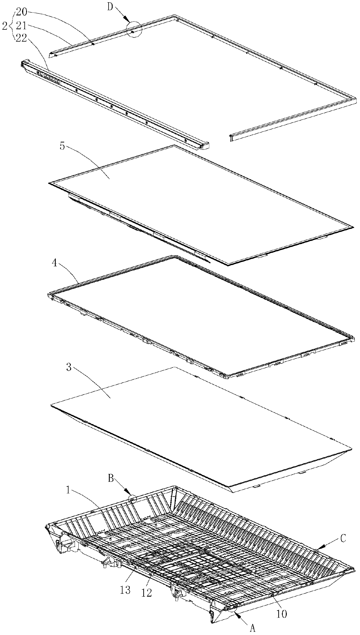
[0006] The object of the present invention is to overcome at least one disadvantage of the above-mentioned prior art, and provide a surface frame installation structure of a liquid crystal display device and a liquid crystal display device, which solves the problem that the surface frame installation structure of an existing liquid crystal display device cannot take into account the ultra-narrow effect and technical issues of aesthetics

Method used


Image

  • Surface frame installation structure of liquid crystal display device and liquid crystal display device
  • Surface frame installation structure of liquid crystal display device and liquid crystal display device
  • Surface frame installation structure of liquid crystal display device and liquid crystal display device

Examples


Embodiment Construction

[0031] In order to make the object, technical solution and advantages of the present invention clearer, the present invention will be further described in detail below in conjunction with the accompanying drawings and embodiments. It should be understood that the specific embodiments described here are only used to explain the present invention, not to limit the present invention.

[0032] It should be noted that when an element is referred to as being “fixed” or “disposed on” another element, it may be directly on the other element or there may be an intervening element at the same time. When an element is referred to as being "connected to" another element, it can be directly connected to the other element or intervening elements may also be present.

[0033] It should also be noted that the orientation terms such as left, right, up, down, top, and bottom in the following examples are only relative concepts or refer to the normal use status of the product, and should not be ...


PUM


Abstract

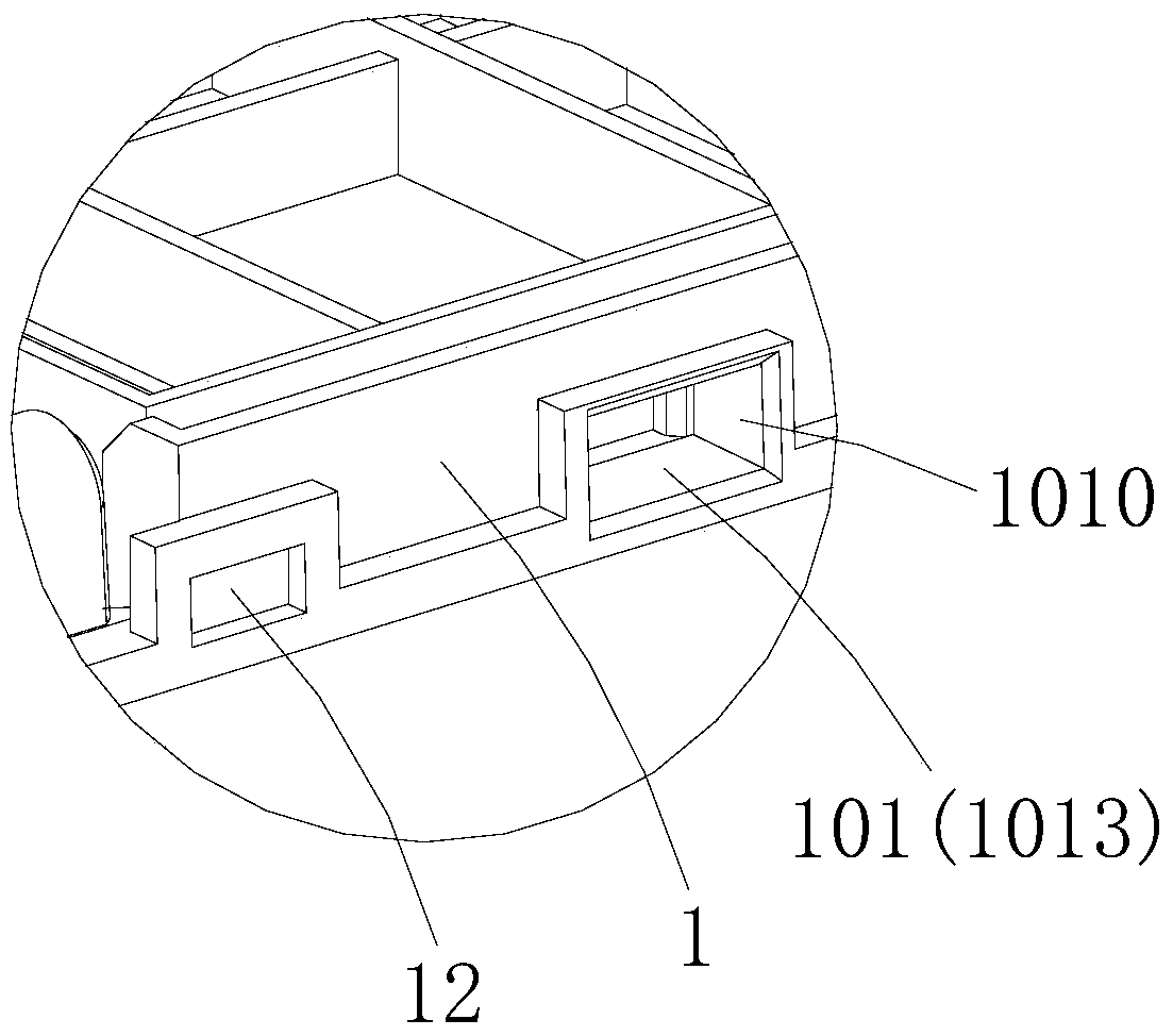
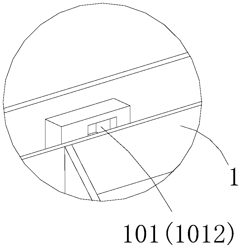
The invention is applicable to the field of liquid crystal display equipment and discloses a face frame installation structure of liquid crystal display equipment and the liquid crystal display equipment. The face frame installation structure of the liquid crystal display equipment comprises a main case shell and a face frame installed on the front side portion of the main case shell, a hole buckling structure is formed in the outer rim of the main case shell in the side direction, a hole locking structure is arranged on the inner wall of the face frame in the side direction in a protruding mode, and the hole locking structure is connected with the hole buckling structure in the side direction in a buckled mode. According to the face frame installation structure of the liquid crystal display equipment and the liquid crystal display equipment, connection between the face frame and the main case shell is achieved in a mode of conducting buckled connection in the side direction, the problem that when the face frame is connected with the main case shell in an existing mode of conducting buckled connection in the forward direction, occupied space is generated due to frame insertion limitation is effectively eliminated, thereby the frame width of a complete machine can be decreased to the greatest extent, meanwhile, the problem that when the face frame is connected with the main case shell in an existing mode of locking screws in the side direction, the screws are exposed in product appearance, so that a bad appearance effect is caused to the entire appearance of a product is solved fundamentally, and finally the effects of giving consideration to super narrowness and super thinness of the product and attractive appearance are finally achieved.

Description

technical field [0001] The invention belongs to the field of liquid crystal display devices, in particular to a surface frame installation structure of a liquid crystal display device and a liquid crystal display device with the surface frame installation structure. Background technique [0002] In the liquid crystal display devices in the existing market, there are roughly three connection methods between the front frame and the main casing: the first is to use front and rear screw locking, that is, to directly lock the screws from the rear of the main casing to the front frame The second method is to use the side screw locking method, that is, to lock the screws from the side of the front frame to the main casing; the third method is to use the front buckle connection method, that is, from the front of the front frame to the middle through the buckle. frame or main chassis. However, these three connection methods of the existing surface frame and the main casing all have ...

Claims


Application Information

Patent Timeline
Patent Type & Authority Patents(China)
IPC IPC(8): G02F1/1333
CPCG02F1/133308G02F1/133328
Inventor 王智勇周友根
Owner HEFEI HUIKE JINYANG TECH
Learn More