Securing device for an optical body for a motor vehicle headlight

A technology of clamping device and headlight, applied in the direction of headlight, signal device, lighting device, etc., can solve problems such as loss

Active Publication Date: 2016-06-08
ZKW GRP GMBH
View PDF2 Cites 5 Cited by
  • Summary
  • Abstract
  • Description
  • Claims
  • Application Information

AI Technical Summary

Problems solved by technology

Here, however, the completely reflective properties of the optical instrument body (that is, the auxiliary optical system of the optical instrument body), part of the loss

Method used


Image

  • Securing device for an optical body for a motor vehicle headlight
  • Securing device for an optical body for a motor vehicle headlight
  • Securing device for an optical body for a motor vehicle headlight

Examples


Embodiment Construction

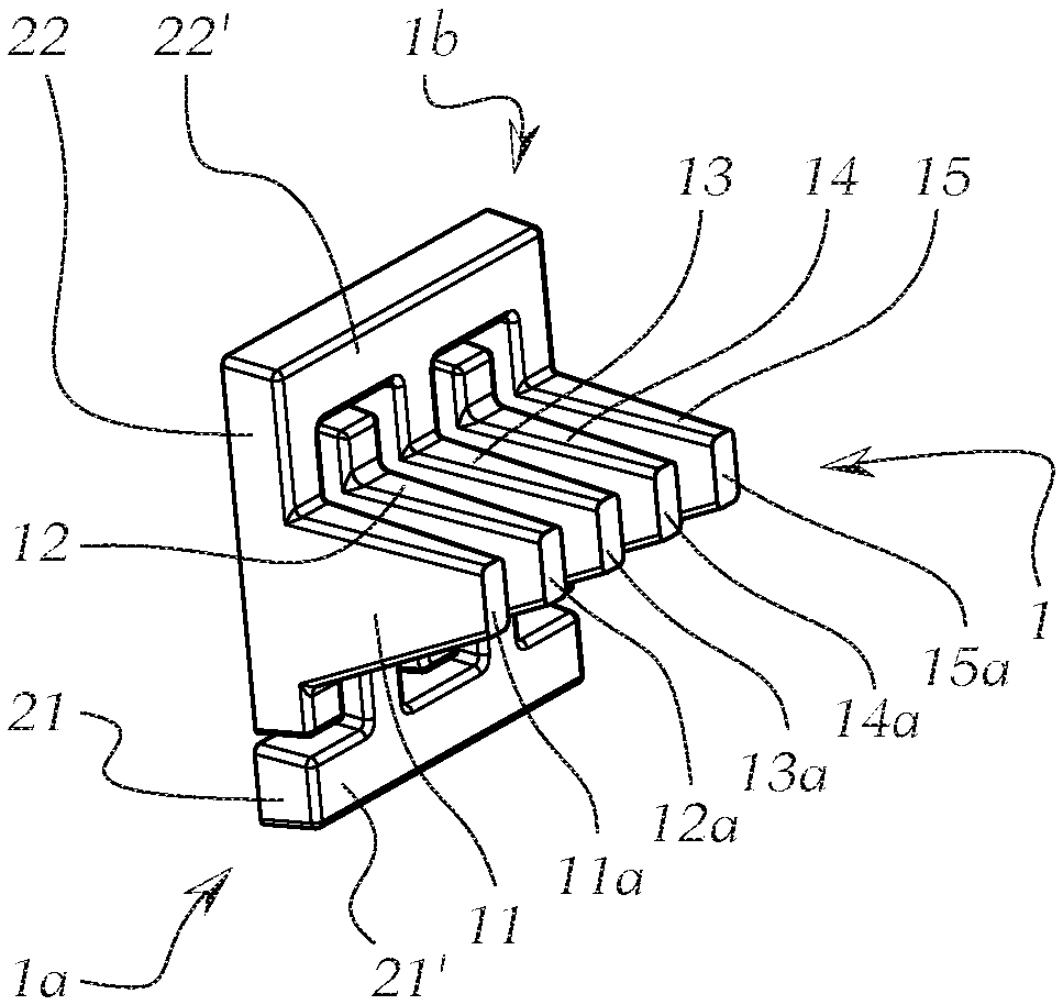
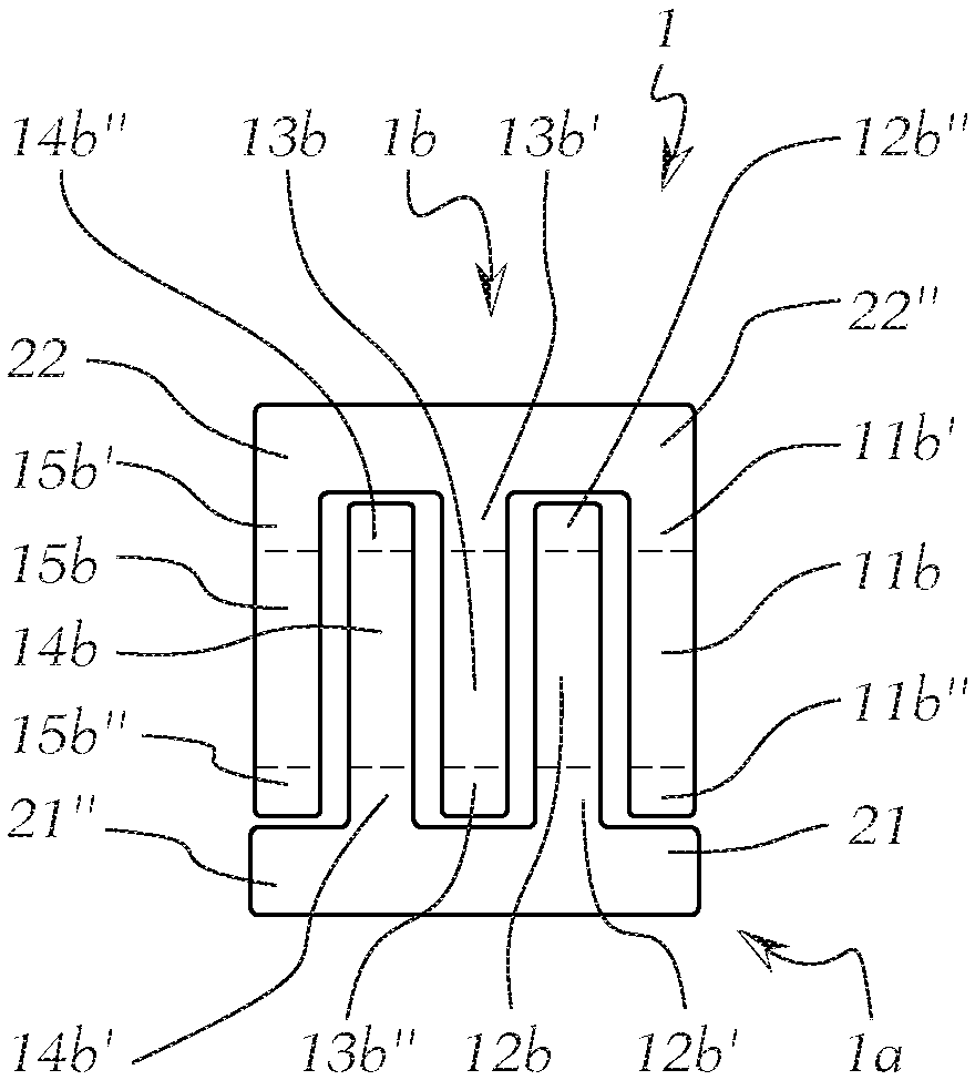
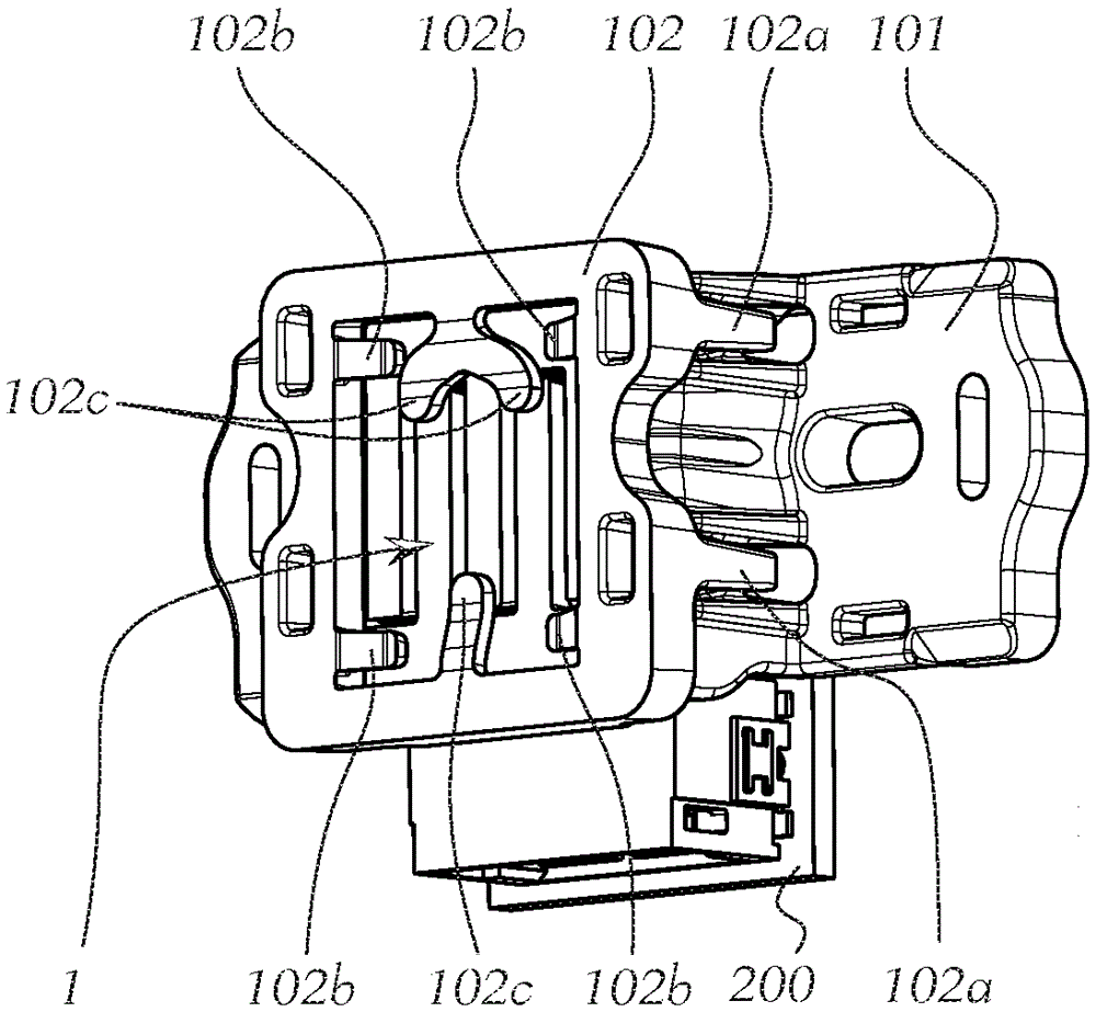
[0061] figure 1 In an assembled state and figure 2 An exploded view shows an optical tool body 1 for a motor vehicle headlight or a clamping device 100 for a light module for a motor vehicle headlight.

[0062] The optical tool body 1 can especially be figure 2 , 5 , 6 and 8 clearly show that the optical tool body includes a certain number of auxiliary optical system 11, 12, 13, 14, 15 arranged side by side, wherein each auxiliary optical system 11-15 All are composed of light guide materials and each auxiliary optical system 11-15 has a light coupling surface 11a-15a ( Figure 5 ) And optocoupler 11b-15b.

[0063] The light coupling-out surfaces 11b-15b of adjacent auxiliary optical tool systems 11-15 here have a distance of a>0 with respect to each other. As shown, the adjacent auxiliary optical tool systems are usually in their entire extended range. The interiors are separated from each other and not only in the region of the light coupling out surface, and are used to preven...


PUM


Abstract

The invention relates to a securing device (100) for an optical body (1) for a motor vehicle headlight or for a light module for a motor vehicle headlight, which optical body (1) has a number of front-end optical systems (11, 12, 13, 14, 15) which are arranged one next to the other, wherein each front-end optical system (11-15) is formed from a light-guiding material, and each front-end optical system (11-15) has a light-input face (11a-15a) and a light-extraction face (11b-15b), wherein the front-end optical systems (11-15) are mechanically connected to one another with at least one connecting web (21, 22), running transversely with respect to the front-end optical systems (11-15), in the region of the light-extraction faces (11b-15b), wherein the at least one connecting web (21, 22) is optically ineffective at least in certain areas, wherein the securing device has a base body (101) with receptacles (121, 122) for the optical body (1), and a securing body (102) which holds the optical body in the base body by means of clamping elements (102b, 102c).

Description

Technical field [0001] The invention relates to an optical tool body (Optikk?rper) used for a motor vehicle headlight (Kraftfahrzeugscheinwerfer) or a clamping device for a light module used for a motor vehicle headlight, the optical tool body has a certain number The auxiliary optical system (Vorsatzoptik) arranged side by side, wherein each auxiliary optical system is composed of a light guide material and each auxiliary optical system has a light coupling in surface (Lichteinkoppelfl?che) and a light coupling out surface (Lichtauskoppelfl?che) Wherein, the auxiliary optical system is mechanically connected to each other in the region of the light coupling out surface with at least one connecting piece extending transversely to the auxiliary optical system; wherein, the at least one connecting piece is at least partially Doesn't work optically. [0002] In addition, the present invention relates to a light module for a headlight of a motor vehicle. The light module includes at ...

Claims


Application Information

Patent Timeline
Patent Type & Authority Applications(China)
IPC IPC(8): F21S8/10F21V8/00F21V5/00F21V17/16
CPCF21S41/24G02B7/00F21S41/29F21S41/60F21S41/663B60Q1/0491B60Q1/0408
Inventor U.迈尔O.雷特格L.陶德特
Owner ZKW GRP GMBH
Why Eureka
Try Eureka