Numerical control double-end lathe

A lathe and double-head technology, applied to turning equipment, turning equipment, automatic in/out of workpieces, etc., can solve problems such as low work efficiency, and achieve the effects of improving efficiency, improving feeding efficiency, and improving maintenance efficiency

Active Publication Date: 2016-06-15
WENLING KEYU AUTOMATION EQUIP CO LTD
View PDF7 Cites 12 Cited by
  • Summary
  • Abstract
  • Description
  • Claims
  • Application Information

AI Technical Summary

Problems solved by technology

However, in the process of loading and unloading shaft parts on the chuck, the work efficiency is low

Method used


Image

  • Numerical control double-end lathe
  • Numerical control double-end lathe
  • Numerical control double-end lathe

Examples


Embodiment Construction

[0058] The present invention will be described in further detail below in conjunction with the accompanying drawings.

[0059] This specific embodiment is only an explanation of the present invention, and it is not a limitation of the present invention. Those skilled in the art can make modifications to this embodiment without creative contribution as required after reading this specification, but as long as they are within the rights of the present invention All claims are protected by patent law.

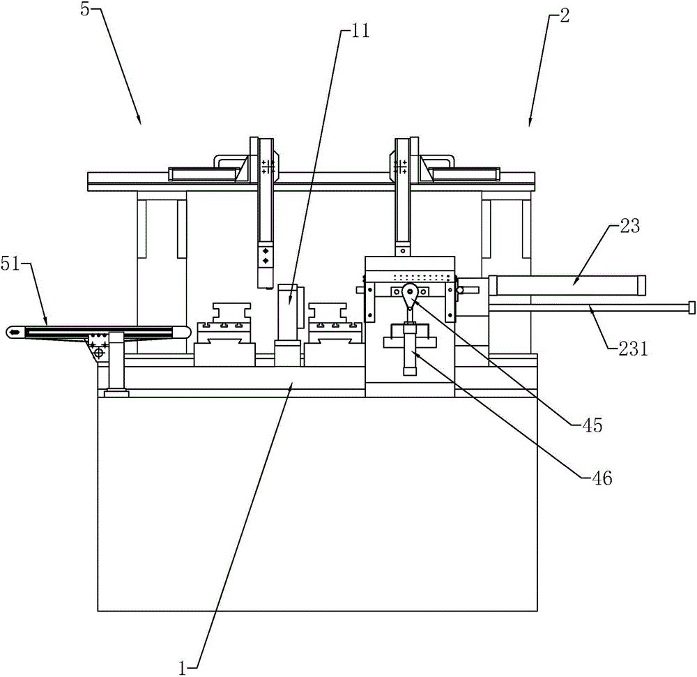
[0060] (CNC double-head lathe), such as figure 1 As shown, the two sides of the chuck 11 are used for piercing and clamping the shaft material 7, wherein the chuck 11 is clamped by a cylinder, and the rotation of the chuck 11 is controlled by a transmission motor.

[0061] The left and right sides of the chuck 11 are respectively provided with a loading mechanism 2 and an unloading mechanism 5 .

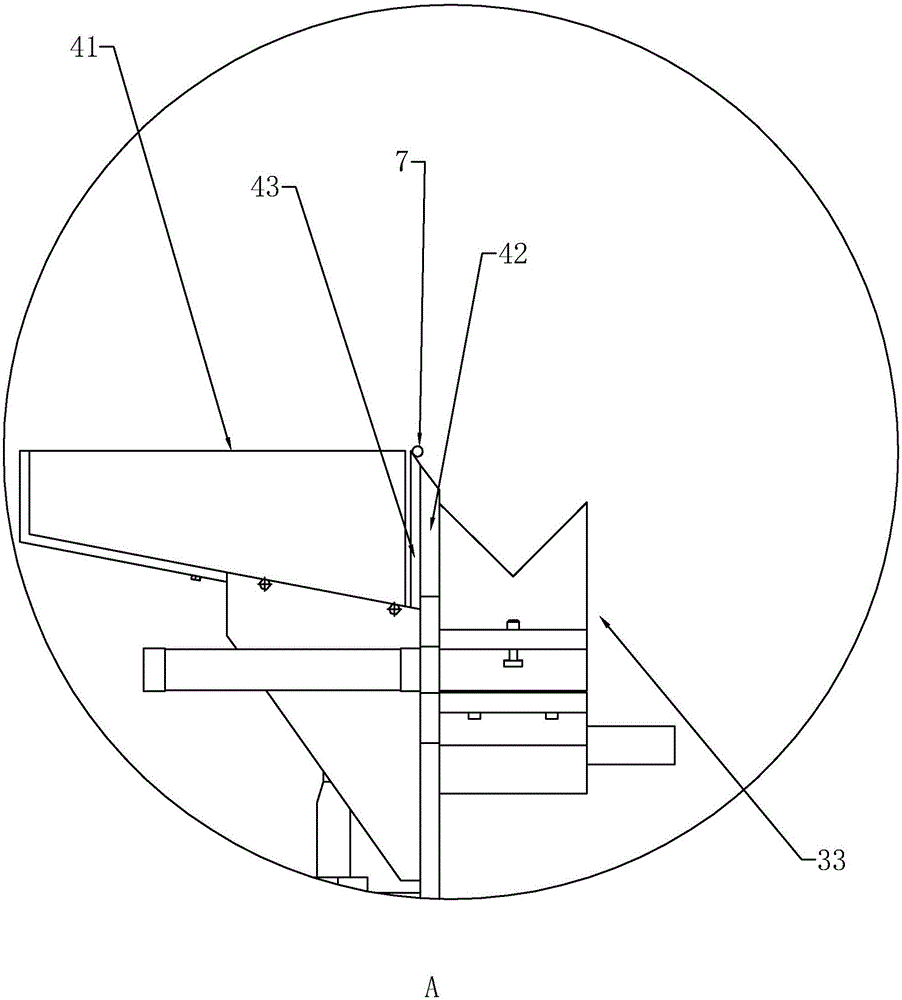
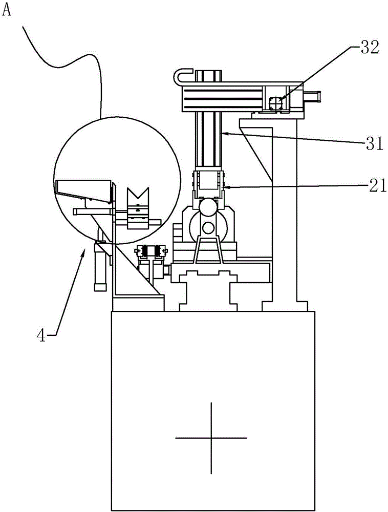
[0062] (Unloading mechanism 5), such as figure 2 and Figure 4 As shown, its ej...


PUM


Abstract

The invention discloses a numerical control double-end lathe, and solves the problems of slow loading and unloading speed and low efficiency of a lathe. The numerical control double-end lathe comprises a base plate provided with chucks, and is characterized in that the chucks are provided with loading mechanisms for feeding the chucks one by one and unloading mechanisms for unloading the chucks one by one; the loading mechanisms include wide air jaws and ejector rods; the wide air jaws are provided with rollers for clamping and guiding materials; the ejector rods push the materials to the chucks along the rollers; the unloading mechanisms include conveying belts for outputting the materials, and clamping air jaws for unloading the chucks; the clamping air jaws feed the materials to the conveying belts; power sources for driving the conveying belts are mounted on the lower belt surfaces of the conveying belts; and the power sources slide in the belt directions to achieve the effect of effectively improving the lathe loading and unloading efficiency.

Description

technical field [0001] The invention relates to lathe processing equipment for shaft parts, in particular to a double-head lathe. Background technique [0002] In the machinery manufacturing industry, cutting the end face of the shaft is a common process. In the prior art, ordinary lathes are often used to cut the end face of the workpiece. This kind of ordinary lathe can only be processed in one direction. If the workpiece needs to be During two-way machining, one end of the workpiece can only be cut first, and then the other end can be cut. For the operator, the continuous loading and unloading operation makes the work intensity high and the efficiency is very low. [0003] Therefore, the market has a lathe that can process parts in both directions at the same time. [0004] A Chinese patent document whose publication number is CN105215379A is now retrieved, a fully automatic numerically controlled double-head lathe. However, the work efficiency is low when the shaft par...

Claims


Application Information

Patent Timeline
Patent Type & Authority Applications(China)
IPC IPC(8): B23B3/30B23B15/00
CPCB23B3/30B23Q7/055B23Q2707/003
Inventor 吴其干
Owner WENLING KEYU AUTOMATION EQUIP CO LTD
Why Eureka
Try Eureka