Laser spot welding device used for lenses

A laser spot welding and lens technology, applied in laser welding equipment, auxiliary devices, welding equipment, etc., can solve the problems of low efficiency, welding with a single lens lens, and the inability to fundamentally improve the welding efficiency of lens lens spot welding, so as to achieve the goal of welding Good firmness, good application prospects, and the effect of improving welding efficiency

Active Publication Date: 2016-06-15
SUZHOU JIALAN ZHIYUAN ELECTRONICS TECH CO LTD
View PDF10 Cites 3 Cited by
  • Summary
  • Abstract
  • Description
  • Claims
  • Application Information

AI Technical Summary

Problems solved by technology

[0003] The purpose of the present invention is to overcome the existing laser spot welding machine, which can only perform single lens lens welding, cannot fundamentally improve the welding efficiency of lens lens spot welding, and the problem of low efficiency

Method used


Image

  • Laser spot welding device used for lenses
  • Laser spot welding device used for lenses
  • Laser spot welding device used for lenses

Examples


Embodiment Construction

[0016] The present invention will be further described below in conjunction with the accompanying drawings. The following examples are only used to illustrate the technical solution of the present invention more clearly, but not to limit the protection scope of the present invention.

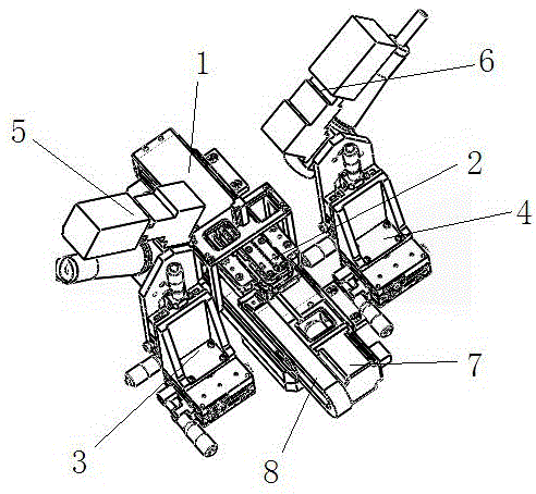
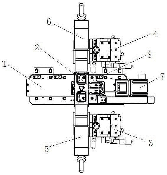
[0017] Such as figure 1 and figure 2 As shown, the laser spot welding device for lens lens of the present invention includes pushing platform 1, lens lens placement jig 2, left spot welding support 3, right spot welding support 4, left laser spot welding machine 5, right laser point The welding machine 6 and the push cylinder 7, the push platform 1 is installed on the sliding table of the welding base, the lens lens placement fixture 2 is clamped on the push platform 1, the left spot welding bracket 3 and the right spot welding bracket 4 are symmetrically arranged on the welding platform. On both sides of the base, the left laser spot welding machine 5 and the right laser spot welding machine...


PUM


Abstract

The invention discloses a laser spot welding device used for lenses. The laser spot welding device comprises a push platform, a lens carrying jig, a left spot welding support, a right spot welding support, a left laser spot welding machine, a right laser spot welding machine and a push air cylinder. The push platform is installed on a sliding table of a welding base. Before welding, the multiple lenses are put on the lens carrying jig, the lens carrying jig on which the lenses are well placed is connected to a feeding platform in a clamped manner, batched laser welding is conducted at a time through the left laser spot welding machine and the right laser spot welding machine under the push of the push air cylinder, the welding firmness is good, the welding efficiency can be greatly improved, and good application prospects are achieved.

Description

technical field [0001] The invention relates to a laser spot welding device for lens lenses, belonging to the technical field of optical fiber component processing. Background technique [0002] The lens lens needs to be welded to the metal base during the production process. The traditional manual spot welding has low production efficiency. In order to improve the welding efficiency, a laser spot welding machine for the lens lens has appeared on the market, but it requires manual labor. After assembling a single lens lens, place it on a laser spot welding machine for laser spot welding. Only one welding can be performed at a time, which still cannot fundamentally improve the welding efficiency of lens lens spot welding. Contents of the invention [0003] The purpose of the present invention is to overcome the problem that the existing laser spot welding machine can only perform single lens lens welding, and cannot fundamentally improve the welding efficiency of the lens...

Claims


Application Information

Patent Timeline
Patent Type & Authority Applications(China)
IPC IPC(8): B23K26/22B23K26/70B23K37/04B23K37/047
CPCB23K26/22B23K37/0461B23K37/047
Inventor 毕延文孙兴元余新文
Owner SUZHOU JIALAN ZHIYUAN ELECTRONICS TECH CO LTD
Why Eureka
Try Eureka