A non-power-limited flow-limiting intelligent interception well with a clapboard slag-retaining device

A technology of interception wells and baffles, applied in the field of interception wells, can provide a direct basis for the design, operation and management of wells and pipelines that cannot be intercepted, the baffles cannot completely intercept floating objects and solid substances, and cannot achieve accurate flow restriction. The interception multiple and other issues can achieve high-efficiency solid interception effect, eliminate daily monitoring tasks, and achieve the effect of quantitative control.

Active Publication Date: 2018-05-11
洼石环境工程(上海)有限公司
View PDF8 Cites 0 Cited by
  • Summary
  • Abstract
  • Description
  • Claims
  • Application Information

AI Technical Summary

Problems solved by technology

The traditional interception wells have the following defects: (1) The flow restriction in the interception well is realized by simple rams or restricted pipe diameters, which cannot achieve accurate flow restriction and ensure the designed interception multiple; (2) The traditional baffles cannot The floating matter and solid matter are completely intercepted, and the passing area of ​​the baffle will gradually decrease with the interception of the floating matter, which will eventually cause the blockage of the baffle; Provide direct basis for the design, operation and management of interception wells and pipelines; (4) Simple and extensive, low management level

Method used


Image

  • A non-power-limited flow-limiting intelligent interception well with a clapboard slag-retaining device
  • A non-power-limited flow-limiting intelligent interception well with a clapboard slag-retaining device
  • A non-power-limited flow-limiting intelligent interception well with a clapboard slag-retaining device

Examples


Embodiment Construction

[0031] The present invention will now be further described in detail in conjunction with the accompanying drawings and embodiments. These drawings are all simplified schematic diagrams, only illustrating the basic structure of the present invention in a schematic manner, so it only shows the composition related to the present invention.

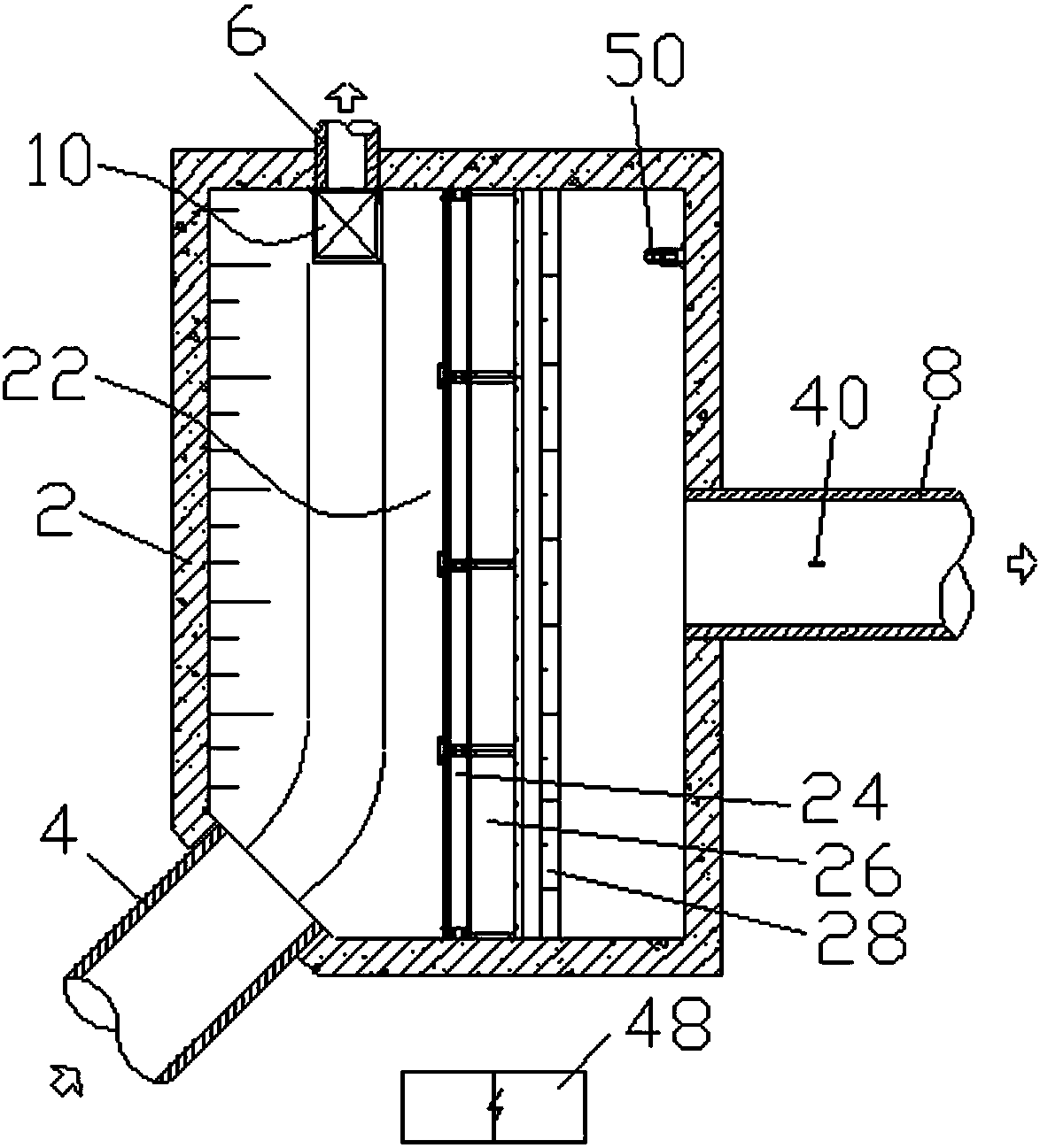
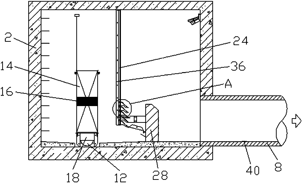
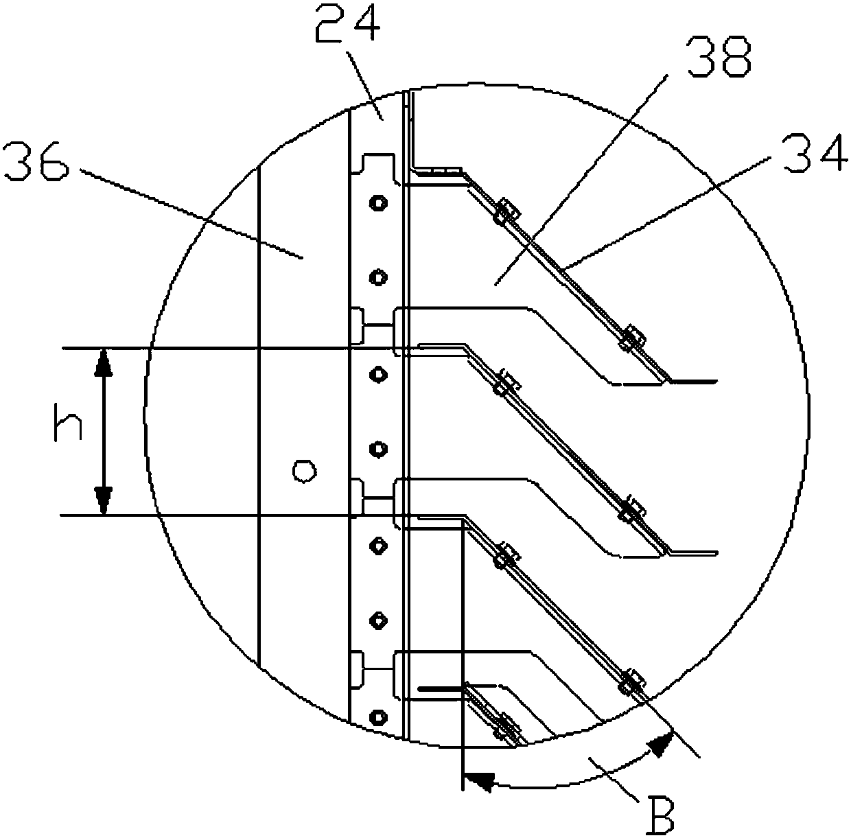
[0032] Such as Figure 1-Figure 3 As shown, a non-powered flow-limiting smart interception well with a partition slag blocking device includes a well body 2, and the side walls of the well body 2 are respectively connected with a sewage inlet pipe 4, an interception sewage pipe 6 and an overflow outlet pipe. 8. A flow limiter 10 is installed in front of the shut-off sewage pipe 6. The flow limiter 10 includes an orifice 12, a chamber 14, a floating ball 16 and a gate 18 in the chamber 14, and the orifice 12 is connected to the shut-off sewage pipe 6 There is a linkage mechanism 20 connected between the floating ball 16 and the flashboard 18. ...


PUM


Abstract

The invention relates to an unpowered current-limiting intelligent intercepting well with a partition board dreg retaining device.The intelligent intercepting well comprises a well body, a sewage inlet pipe, an intercepting sewage pipe and an overflow water outlet pipe are arranged on the side wall of the well body in a communicating mode, and a current limiter is arranged in front of the intercepting sewage pipe.The current limiter comprises a hole, a box chamber, a floating ball and a flashboard, the floating ball and the flashboard are arranged in the box chamber.The hole is communicated with the intercepting sewage pipe, a linkage mechanism is arranged between the floating ball and the flashboard, the floating ball ascends or descends to drive the flashboard to descend or ascend, and the partition board dreg retaining device is arranged in front of the overflow water outlet pipe.The partition board dreg retaining device comprises a baffle, an inclined partition board below the baffle, and an overflow weir opposite to the inclined partition board.The intelligent intercepting well can precisely limit flow.Due to the arrangement of the inclined partition board, the efficient solid interception effect is achieved by preventing the horizontal flowing or a suction effect.A control mechanism is arranged in the box chamber, the risk that current limitation of the floating ball fails is avoided, and the current limiter can adapt to smaller well bodies.

Description

technical field [0001] The invention relates to the technical field of interception wells, in particular to an unpowered flow-limiting intelligent interception well with a clapboard slag-retaining device. Background technique [0002] For the combined drainage pipe network or the separate rainwater pipe network, because the mixed sewage or initial rainwater carries a large amount of particulate pollutants from sources such as urban surfaces, roofs, domestic sewage, and pipeline sediments, it is directly discharged without any interception treatment Entering the receiving water body of the city will cause pollution to the receiving water body. Therefore, it is necessary to intercept the combined pipe network or the separate rainwater pipe network, and set a certain interception multiple so that the intercepted sewage or initial rainwater is discharged into the terminal sewage treatment plant, and the water exceeding the interception capacity is discharged into the surface wat...

Claims


Application Information

Patent Timeline
Patent Type & Authority Patents(China)
IPC IPC(8): E03F5/10E03F5/14
CPCE03F5/10E03F5/107E03F5/14E03F2201/20
Inventor 朱清漪
Owner 洼石环境工程(上海)有限公司
Why Eureka
Try Eureka