
Improved structure of two-way spiral extrusion and expansion drilling tool and construction method of rough-surface extrusion and expansion pile

A two-way helix and improved structure technology, which is applied in basic structure engineering, drilling equipment and methods, sheet pile walls, etc., can solve the waste of pile material, the performance of pile material is not fully exerted, and the soil side soil of the pile cannot be further improved. For problems such as pile side resistance, it can improve the bearing capacity of the pile, increase the construction difficulty and material cost, and increase the side resistance.

Inactive Publication Date: 2016-06-15
刘淼
View PDF6 Cites 0 Cited by
  • Summary
  • Abstract
  • Description
  • Claims
  • Application Information

AI Technical Summary

Problems solved by technology

However, due to the cylindrical shape of the pile, the performance of the pile material has not been fully utilized, and the lateral resistance of the pile side soil to the pile cannot be further improved, resulting in a waste of pile material

Method used


Image

  • Improved structure of two-way spiral extrusion and expansion drilling tool and construction method of rough-surface extrusion and expansion pile
  • Improved structure of two-way spiral extrusion and expansion drilling tool and construction method of rough-surface extrusion and expansion pile
  • Improved structure of two-way spiral extrusion and expansion drilling tool and construction method of rough-surface extrusion and expansion pile

Examples


Embodiment Construction

[0026] The following will clearly and completely describe the technical solutions in the embodiments of the present invention with reference to the accompanying drawings in the embodiments of the present invention. Obviously, the described embodiments are only some, not all, embodiments of the present invention. Based on the embodiments of the present invention, all other embodiments obtained by persons of ordinary skill in the art without making creative efforts belong to the protection scope of the present invention.

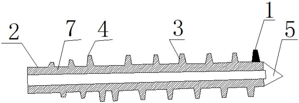
[0027] Such as figure 1 As shown, an improved structure of a two-way helical extrusion and expansion drilling tool, the upper part of the two-way helical extrusion and expansion drilling tool 2 is integrally formed with a soil extrusion screw 4 opposite to the direction of the lower drilling screw, and the lower part is integrally formed with a drilling screw 3. A drill tip 5 is connected to the lower part of the two-way helical extrusion drilling tool 2; the ...


PUM


Abstract

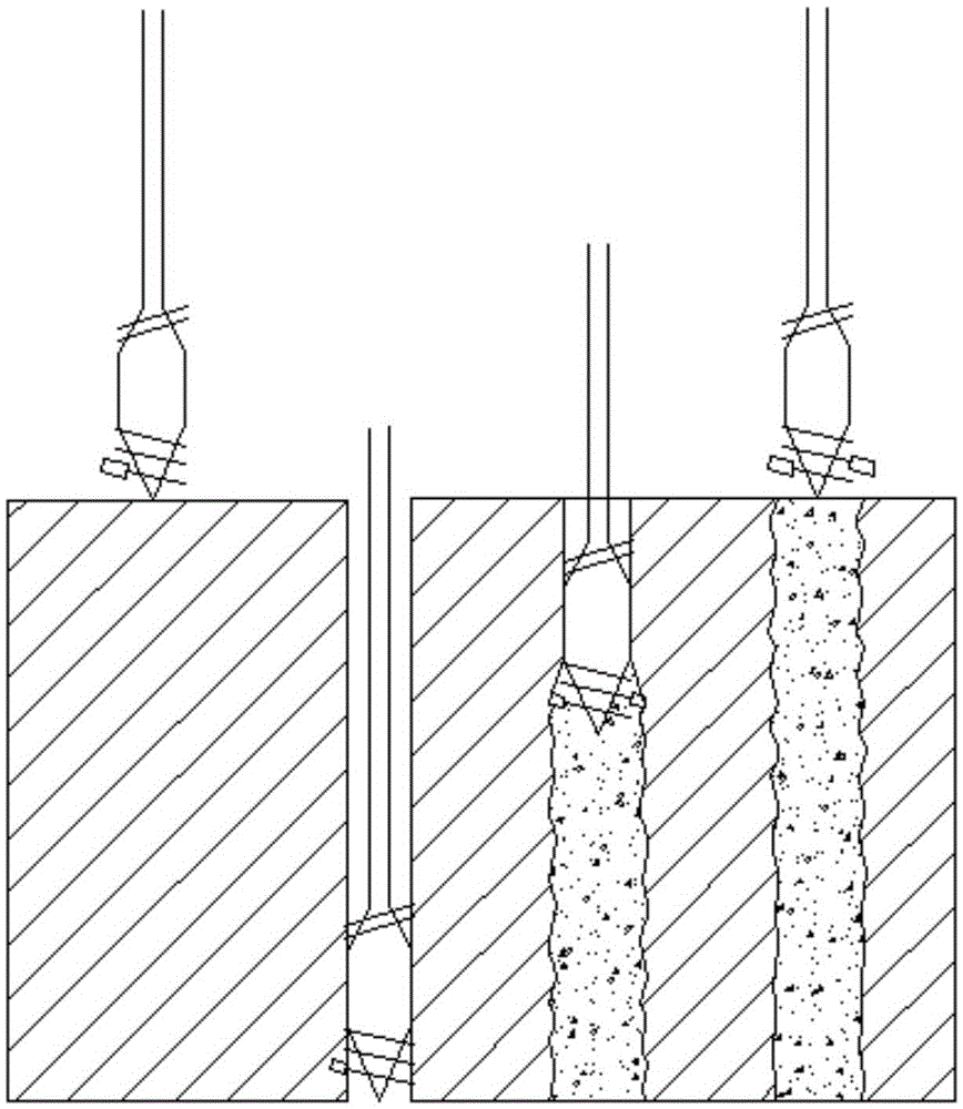
The invention discloses an improved structure of a two-way spiral extrusion and expansion drilling tool.A drilling spiral piece (3) is integrally formed on the lower portion of the two-way spiral extrusion and expansion drilling tool (2).A soil extrusion spiral piece (4) in the reversed direction is integrally formed on the upper portion of the two-way spiral extrusion and expansion drilling tool (2).A drill tip (5) is connected with the lower portion of the two-way spiral extrusion and expansion drilling tool.A soil sweeping thread (1) is formed in the two-way spiral extrusion and expansion drilling tool.The height at which the soil sweeping thread is perpendicular to the two-way spiral extrusion and expansion drilling tool is larger than the height of the highest point of the cross section of the two-way spiral extrusion and expansion drilling tool.When forward lift drilling is conducted and concrete is pumped for pile forming at the same time through the two-way spiral extrusion and expansion drilling tool with the improved structure and the construction method, a two-way extrusion and expansion threaded pile with threads can be formed through synchronous lifting, and a rough-surface extrusion and expansion cast-in-place pile with irregular concrete protrusions on the pile body can be formed through non-synchronous lifting.By means of the spiral cast-in-place pile, the soil extrusion effect is achieved, the side resistance of soil beside the pile to the pile is further increased, and therefore the pile bearing capacity can be improved by 20% or above without increasing construction difficulty and material cost.

Description

technical field [0001] The invention relates to an improved structure of a drilling tool and a construction method of a pile, in particular to an improved structure of a two-way spiral extruded and expanded drilling tool and a construction method for a rough surface spiral extruded and expanded pile, belonging to the technical field of construction engineering. Background technique [0002] With the development of the economy and the scarcity of land resources, buildings are gradually developing towards high-rise buildings, and the loads of buildings and structures are increasing, making pile types with higher bearing capacity, pile-forming devices, and construction methods widely used in foundation engineering . [0003] According to the effect of the pile-forming method on the soil layer, piles can be divided into three categories: soil-squeezed piles, partially-squeezed piles and non-squeezed piles. Most of the existing cast-in-place pile construction follows the traditi...

Claims


Application Information

Patent Timeline
IPC IPC(8): E21B7/00E21B7/28E02D5/36E02D5/56
CPCE21B7/00E02D5/36E02D5/56E02D2250/0023E21B7/28
Inventor 刘淼刘昭运刘亚璞
Owner 刘淼
Learn More