Servo system, and encoder

An image and lens technology, applied in the field of arrays together, can solve problems such as difficult to control spacing and easy self-contamination

Active Publication Date: 2016-06-15
LUMENCO
View PDF6 Cites 12 Cited by
  • Summary
  • Abstract
  • Description
  • Claims
  • Application Information

AI Technical Summary

Problems solved by technology

Typically, for element 200, the microlenses are printed using an emboss and fill technique, which limits printing to one color due to the fact that the process is prone to self-...

Method used


Image

  • Servo system, and encoder
  • Servo system, and encoder
  • Servo system, and encoder

Examples


Embodiment Construction

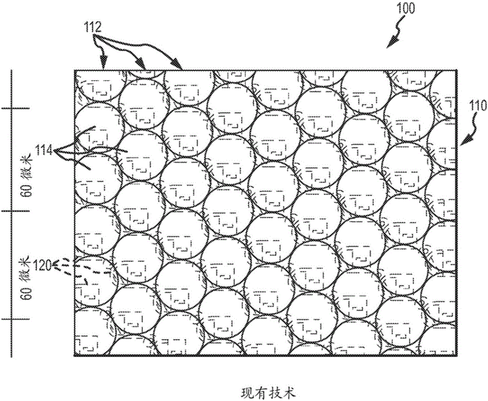
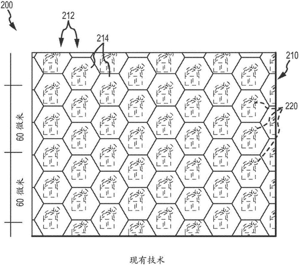
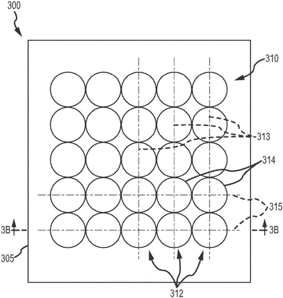
[0043] Briefly, the description is directed to the design of components of a lens array for combination with a printed image provided in an ink layer. The assembly may be used as, for example but not limited to, a security element or device. lens array with figure 1 and figure 2 The lens arrays shown in are partly different in that the lenses are arranged in columns that are not vertically offset, such that the lenses are provided in parallel columns and also in parallel rows (e.g., adjacent columns in side-by-side columns lenses are aligned on their collinear central axes). The lenses may be circular-based, square-based, parallelogram-based, or hexagon-based, and the underlying image has its pixels mapped and arranged such that the microlens array produces a 3D display image with full volume and, in some cases, Multidirectional movement or animation.

[0044] exist Figure 3A and Figure 3B In the illustrated embodiment, an item 300 (such as a banknote, a label for a p...


PUM


Abstract

To inhibit an increase in the number of encoder types. [Solution] A servo system (S) is provided with: a motor (M) configured such that a movable element moves relative to a stator; an encoder (100) configured so as to detect a position of the movable element; and a control device (CT) configured so as to control operation of the motor (M) on the basis of a detection result of the encoder (100). The control device (CT) is provided with a first command transmission unit (210A) configured so as to transmit, to the encoder (100), at a first speed, a change command for changing an encoder-side communication speed to a second speed which is faster than the current first speed. The encoder (100) is provided with a speed setting unit (111) configured so as to change the encoder-side communication speed to the second speed in cases when the change command has been received.

Description

[0001] Cross References to Related Applications [0002] This application is a continuation-in-part of U.S. Patent Application No. 14 / 017,415, filed September 4, 2013, which claims the benefit of U.S. Provisional Application No. 61 / 743,485, filed September 5, 2012, which Both applications are hereby incorporated by reference in their entirety. technical field [0003] The present invention relates generally to combining printed images with lens arrays to display three-dimensional (3D) images with or without motion, and more particularly to a method suitable for use with square-, circular-, parallelogram- or hexagon-based Arrays of microlenses are used together to provide pixel mapping with more complete volume and / or enhanced 3D imagery with multi-directional motion, providing an arrangement of pixels and a method of imaging. Background technique [0004] There are currently many applications in which it is desirable to view a printed image through an array of lenses. For ...

Claims


Application Information

Patent Timeline
IPC IPC(8): G02B27/22H04N13/04H04N13/307
CPCB42D25/324B42D25/342G02B3/0056B42D25/29B42D25/351H04N13/307B42D25/30
Inventor M.A.雷蒙德H.A.P.索托
Owner LUMENCO
Why Eureka
Try Eureka