Electric connector set

A technology of electrical connectors and electrical joints, which is applied in the direction of connection, components of connection devices, circuits, etc., can solve the problem of expensive electrical connector groups, and achieve the effect of material saving and satisfactory connection

Active Publication Date: 2016-06-15
SCHNEIDER ELECTRIC IND SAS
View PDF5 Cites 2 Cited by
  • Summary
  • Abstract
  • Description
  • Claims
  • Application Information

AI Technical Summary

Problems solved by technology

[0006] The electrical connector set is relatively expensive due to the relatively large size of the first magnetic element equipped with the receptacle to fit the pins into the space defined by its annular shape

Method used


Image

  • Electric connector set
  • Electric connector set
  • Electric connector set

Examples


Embodiment Construction

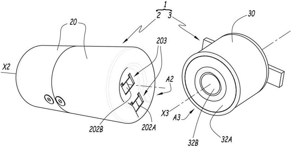
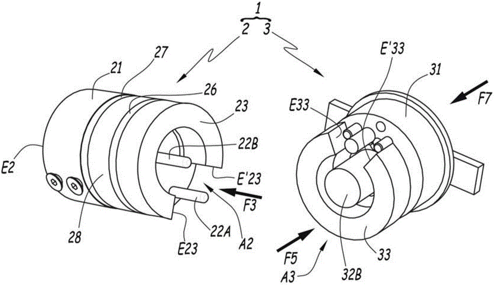
[0033] figure 1 and 2 An electrical connector set 1 is shown comprising an electrical socket 2 and an electrical plug 3 adapted to electrically and mechanically engage the electrical socket in a removable manner. The socket 2 and the plug 3 each include an outer cover 20 or 30, which only figure 1 shown in .

[0034] In the example used, the socket 2 is connected to the grid and the plug 3 is equipped with an appliance to be used in the home, such as a lamp or a household appliance. Thus, the socket 2 is normally stationary, while the plug 3 is active.

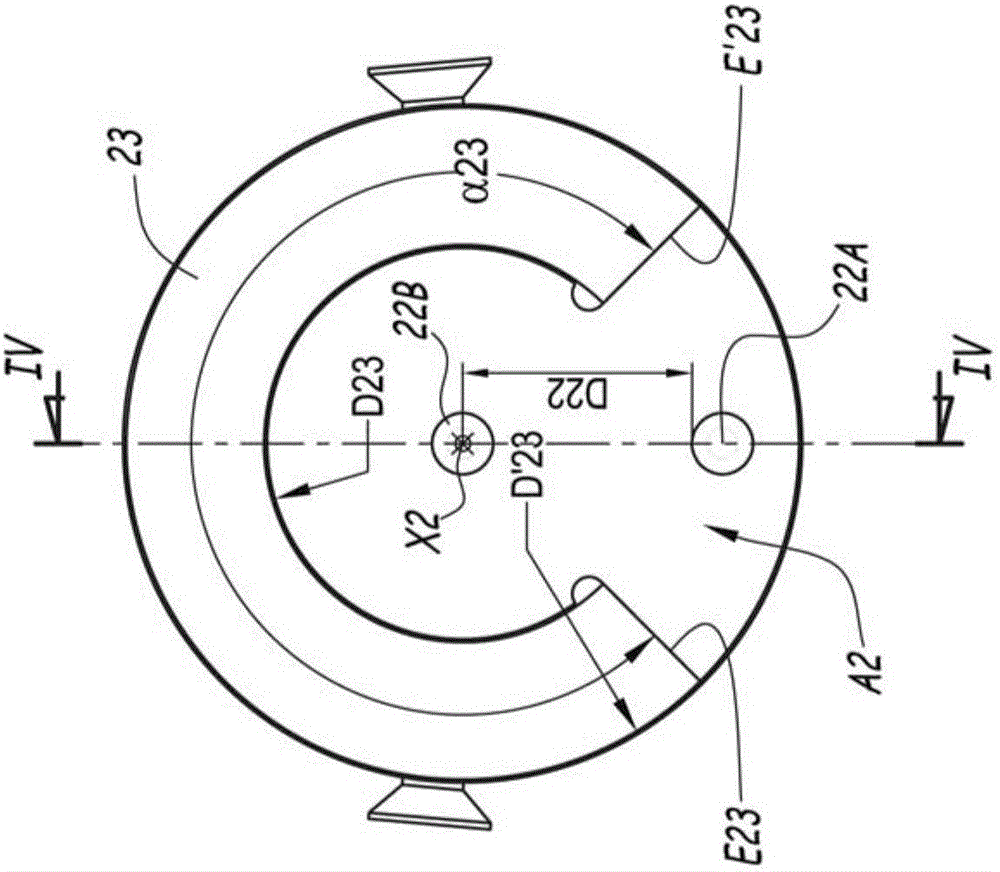
[0035] The socket 2 and the plug 3 each comprise a main body 21 or 31 accommodated inside the outer cover 20 or 30, and a substantially flat contact surface A2 or A3. The contact surfaces A2 and A3 are designed to be arranged in contact with each other when the plug 3 is connected to the socket 2 .

[0036] The socket 2 and the plug 3 can each extend along a central longitudinal axis X2 or X3. To electrically connect soc...


PUM

PropertyMeasurementUnit
electrical conductivityaaaaaaaaaa

Abstract

The invention relates to an electric power outlet unit (1) which comprises an electric junction socket (2) and an electric plug (3) which is suitable for detachably connecting with the socket (2) electrically. The socket (2) comprises at least one first contact and a second contact (22A,22B). The contacts respectively have a first concentric contact and a second concentric tracks (32A,32B) of the plug (3). The contacts (22A,22B) are movable between a first position where the contacts are retracted to inside of the socket (2) and a second position where the contacts are projected from the socket (2). The socket (2) is provided with a first magnetic element (23) which is suitable for connecting with a second magnetic element (33) which is mounted on the plug (3), thereby generating a magnetic force. The magnetic force is suitable for positioning and keeping the plug relative to the socket (2) and is used for moving the contacts (22A,22B) to the second position, thereby establishing electric contact between an electric track (32B) and the contacts (22A,22B). The first magnetic element (23) has an annular shape and furthermore the first electric track is made a material which is suitable for guiding the magnetic field that is generated by the magnetic elements (23,33) in a process of connecting the plug (3) with the socket (2).

Description

technical field [0001] The present invention relates to an electrical connector set comprising an electrical receptacle and an electrical plug adapted to removably electrically engage the electrical receptacle. Background technique [0002] Electrical sockets are traditionally fixed to the walls of buildings and connected to the grid, and electrical plugs are equipped with electrical devices powered by current from the grid. An electrical plug includes two protruding pins for insertion into complementary recessed openings provided in an electrical receptacle. The disadvantage of this manipulation is that the user must correctly position the pins in the openings, which is tedious. Furthermore, the operator must provide relatively high force to push the pins into the openings. [0003] FR-A-2964501 discloses an electrical connector set equipped with magnetic positioning elements to avoid the user having to orient the pins correctly and to facilitate electrical connections. ...

Claims


Application Information

Patent Timeline
Patent Type & Authority Applications(China)
IPC IPC(8): H01R13/62H01R13/453H01F7/02H01R13/629
CPCH01F7/0263H01R13/4532H01R13/6205H01R13/629
Inventor C.布朗德尔
Owner SCHNEIDER ELECTRIC IND SAS
Why Eureka
Try Eureka