Supercharge Your Innovation With Domain-Expert AI Agents!

Bearing pedestal surface grinding equipment facilitating chip removal

A technology for surface grinding and bearing housing, which is used in grinding/polishing equipment, metal processing equipment, grinding machines, etc., which can solve the problems of dust, increase labor and time costs, and take a long time for bearing housings.

Inactive Publication Date: 2016-06-22
周胡琴
View PDF8 Cites 0 Cited by
  • Summary
  • Abstract
  • Description
  • Claims
  • Application Information

AI Technical Summary

Problems solved by technology

[0002] The bearing seat is a mounting component used to fix various bearings. During the processing of the bearing seat, the surface of the bearing seat needs to be ground. The traditional grinding method is to place a single bearing seat on a designated fixture, start the grinding machine, and stop the machine after grinding. Finished products, this kind of processing method takes a long time to process a large number of bearing seats and requires a large number of staff, which greatly increases labor and time costs. After grinding, a large amount of dust will be generated. It is necessary to deal with this part of dust in time to avoid It affects the normal operation of the equipment, and also prevents dust from accumulating on the inner wall of the protective cover, affecting the staff to observe the working conditions in the protective cover. The traditional method uses manual cleaning. On the one hand, it needs to be shut down. On the other hand, the airflow in the working environment will cause dust, which affects working environment

Method used


Image

  • Bearing pedestal surface grinding equipment facilitating chip removal
  • Bearing pedestal surface grinding equipment facilitating chip removal
  • Bearing pedestal surface grinding equipment facilitating chip removal

Examples


Embodiment Construction

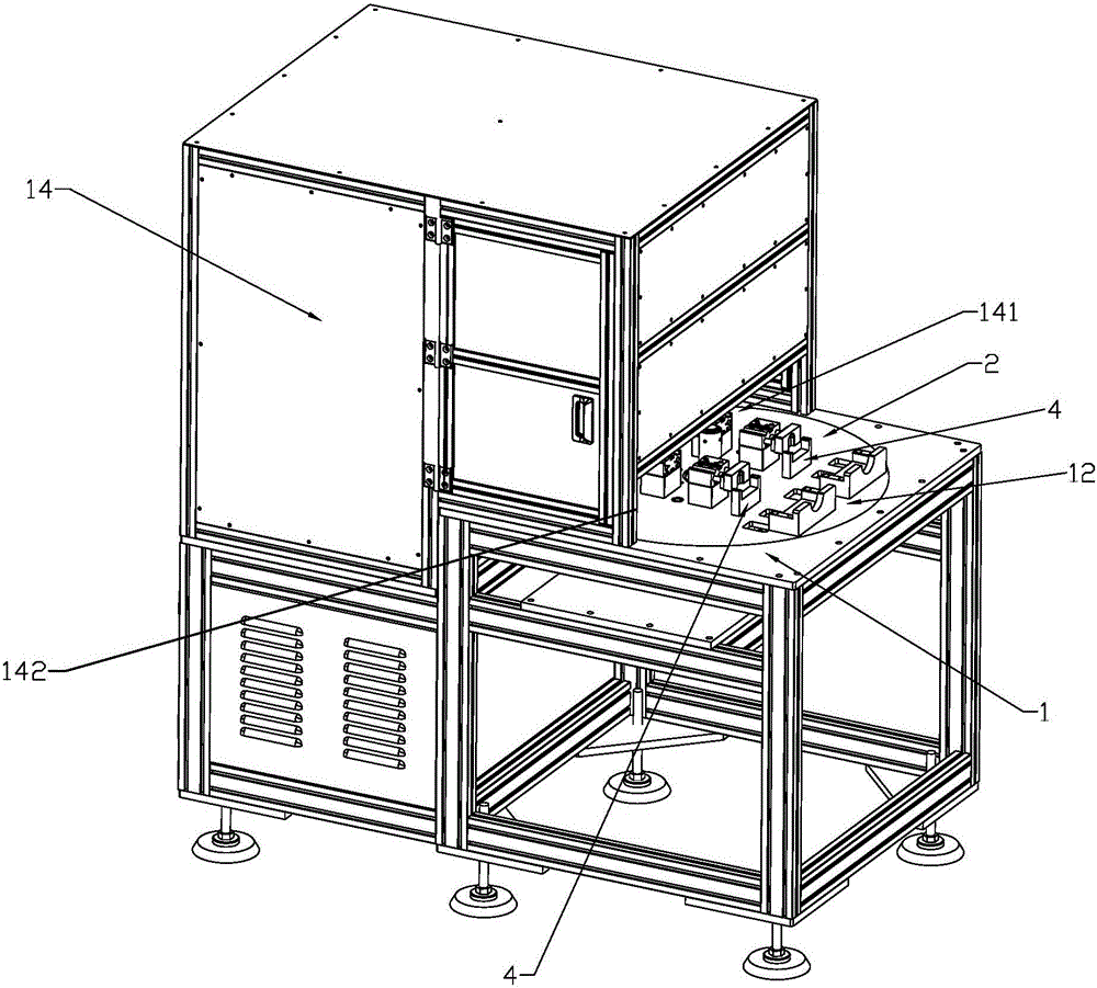
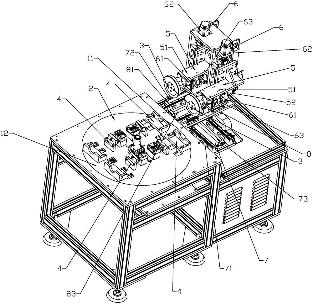
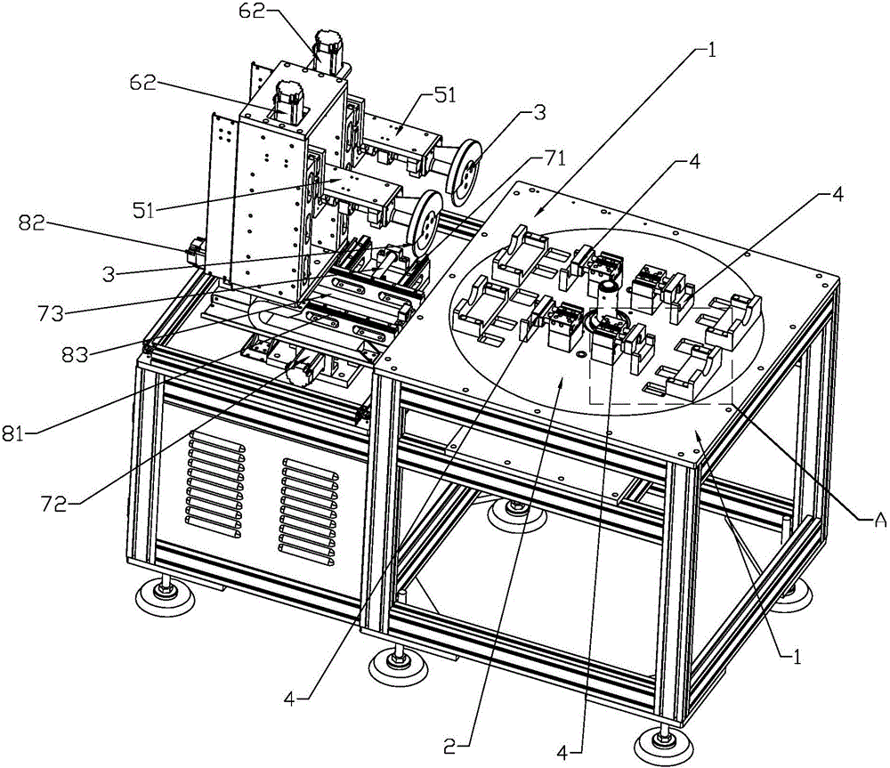
[0025] Such as figure 1 — Figure 6 As shown, the present invention discloses a surface grinding device for chip removal bearing housing, which includes a workbench 1, a main turntable 2, a main turntable rotation mechanism, a bearing seat fixing device, a grinding disc 3, a grinding disc rotation mechanism, and a grinding disc displacement mechanism, the main turntable rotation mechanism is a geared motor 22, the main turntable rotation mechanism is fixed on the workbench 1 and drives the main turntable 2 to rotate horizontally on the workbench 1, and the grinding disc displacement mechanism is fixed on the workbench 1 to drive the grinding disc 3 and grind The disc rotation mechanism is close to and away from the main turntable 2. The worktable 1 is provided with a processing position 11 corresponding to the position of the grinding disc 3 and a refueling position 12 far away from the grinding disc 3 on the moving track of the main turntable. The upper end of the main turnta...


PUM


Abstract

The invention relates to bearing pedestal surface grinding equipment facilitating chip removal. The bearing pedestal surface grinding equipment comprises a working table, a main rotating disc, a main rotating disc rotating mechanism, bearing pedestal fixing devices, a grinding disc, a grinding disc rotating mechanism and a grinding disc shifting mechanism; a chip removal hopper is arranged at the position, located below the main rotating disc, of the working table in the vertical direction, the upper end of the chip removal hopper corresponds to the machining station position of the working table, chip removal openings are formed in the positions, corresponding to the bearing pedestal fixing devices, of the main rotating disc in a penetrating manner in the vertical direction, and a plurality of dust raising prevention plates are arranged in the chip removal hopper; the dust raising prevention plates are arranged on the two sides inside the chip removal hopper at intervals in the axial direction of the chip removal hopper; one end of each dust raising prevention plate is fixed to the inner wall of the chip removal hopper, and the other end of each dust raising prevention plate extends towards the center of the chip removal hopper and gradually descends; and the adjacent dust raising prevention plates coincide relative to the vertical portion. By the adoption of the scheme, according to the bearing pedestal surface grinding equipment facilitating chip removal, dust is prevented from being accumulated in the equipment, and dust raising is prevented.

Description

technical field [0001] The invention relates to a bearing housing processing equipment, in particular to a bearing housing surface grinding equipment which is convenient for chip removal. Background technique [0002] The bearing seat is a mounting component used to fix various bearings. During the processing of the bearing seat, the surface of the bearing seat needs to be ground. The traditional grinding method is to place a single bearing seat on a designated fixture, start the grinding machine, and stop the machine after grinding. Finished products, this kind of processing method takes a long time to process a large number of bearing seats and requires a large number of staff, which greatly increases labor and time costs. After grinding, a large amount of dust will be generated, which needs to be disposed of in time to avoid It affects the normal operation of the equipment, and also prevents dust from accumulating on the inner wall of the protective cover, affecting the s...

Claims


Application Information

Patent Timeline
IPC IPC(8): B24B27/00B24B41/06B24B47/12B24B47/04B24B55/06
CPCB24B27/0023B24B41/066B24B47/04B24B47/12B24B55/06
Inventor 不公告发明人
Owner 周胡琴
Features
  • R&D
  • Intellectual Property
  • Life Sciences
  • Materials
  • Tech Scout
  • Unparalleled Data Quality
  • Higher Quality Content
  • 60% Fewer Hallucinations
Learn More