Check patentability & draft patents in minutes with Patsnap Eureka AI!

Cone container supporting structure

A technology of support structure and cone, applied in the field of support structure, can solve the problems of high strength requirement of upper wall plate and deformation of lower cone wall plate under pressure, and achieve the effect of reducing force and preventing deformation.

Active Publication Date: 2016-06-22
GUANGDONG SINID TECH
View PDF12 Cites 0 Cited by
  • Summary
  • Abstract
  • Description
  • Claims
  • Application Information

AI Technical Summary

Problems solved by technology

This structure has high requirements on the strength of the upper wall, and the lower cone has no support points. When the cone is filled with objects, the lower cone wall will also be deformed under compression.

Method used


Image

  • Cone container supporting structure
  • Cone container supporting structure
  • Cone container supporting structure

Examples


Embodiment Construction

[0009] The present invention will be further described in detail with reference to the accompanying drawings and embodiments:

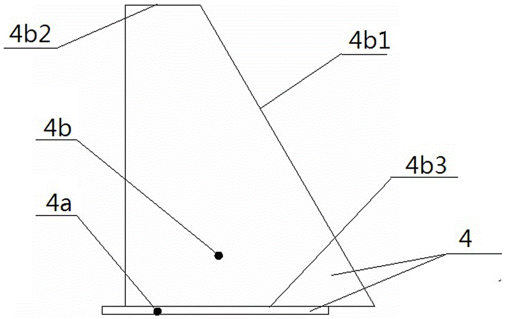
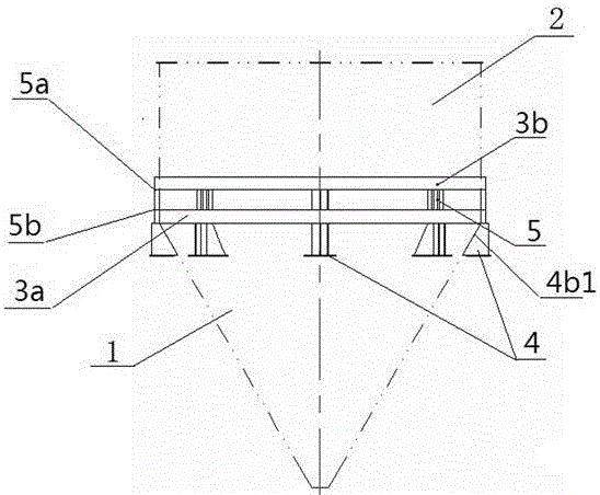
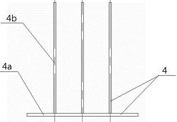
[0010] As shown in the figure, the present invention includes two channel steel rings fixed on the outer side wall of the upper cylindrical container 2 of the cone 1 by welding up and down. The special feature is that a number of support members are provided around the lower side of the next channel steel ring 3a 4. The support 4 includes a bottom steel plate 4a placed horizontally and two or more trapezoidal steel plates 4b fixed side by side and vertically on the bottom steel plate 4a. The hypotenuse 4b1 of the trapezoidal steel plate 4b is welded and fixed to the outer surface of the cone 1, and the trapezoidal steel plate 4b The upper side 4b2 is welded to the bottom of the next channel steel ring 3a, and the lower side 4b3 of the trapezoidal steel plate 4b is welded and fixed to the horizontally placed bottom steel plate 4a. A rectangular steel plate...


PUM


Abstract

The invention discloses a cone container supporting structure. The cone container supporting structure is characterized by comprising two channel steel rings which are fixed onto the outer side wall of a cylindrical container on the upper part of a cone up and down by welding, wherein a plurality of supporting parts are arranged at the periphery of the lower surface of the lower channel steel ring; each supporting part comprises a bottom steel plat which is horizontally placed, and two or more trapezoidal steel plates which are perpendicularly fixed to the bottom steel plate side by side, wherein the bevel edges of the trapezoidal steel plates are fixed to the outer side surface of the cone, the upper sides of the trapezoidal steel plates are fixed to the lower surface of the lower channel steel ring, the lower sides of the trapezoidal steel plates are fixed to the bottom steel plate which is horizontally placed by welding; a rectangular steel plate is arranged on a position, which corresponds to each trapezoidal steel plate, between two the channel steel rings; and the upper side and the lower side of the rectangular steel plate are separately welded on the lower surface of the upper channel steel ring and the upper surface of the lower channel steel ring. Compared with the prior art, the cone container supporting structure has the advantages that the cone can be prevented from being deformed by pressing, and strength requirements on the upper wall plate of the cone container are not high.

Description

Technical field: [0001] The invention relates to a supporting structure. Background technique: [0002] The current cone support structure is to add grooved steel rings around the cone, and then evenly distribute the rectangular pipes connecting the cone supports under the channel steel rings, thereby supporting the cone. This structure has high requirements for the strength of the upper wall plate, and the lower cone part has no supporting point. When the cone is filled with objects, the lower cone wall plate will also be compressed and deformed. Summary of the invention: [0003] The purpose of the present invention is to provide a cone container support structure that can prevent the cone from being deformed due to pressure, and does not require too much strength on the upper wall of the cone container. [0004] The present invention is realized in this way, including two channel steel rings fixed on the outer side wall of the cylindrical container on the upper part of the cone ...

Claims


Application Information

Patent Timeline
IPC IPC(8): B65D90/12
CPCB65D90/12
Inventor 杨扬
Owner GUANGDONG SINID TECH
Features
  • R&D
  • Intellectual Property
  • Life Sciences
  • Materials
  • Tech Scout
  • Unparalleled Data Quality
  • Higher Quality Content
  • 60% Fewer Hallucinations
Learn More