
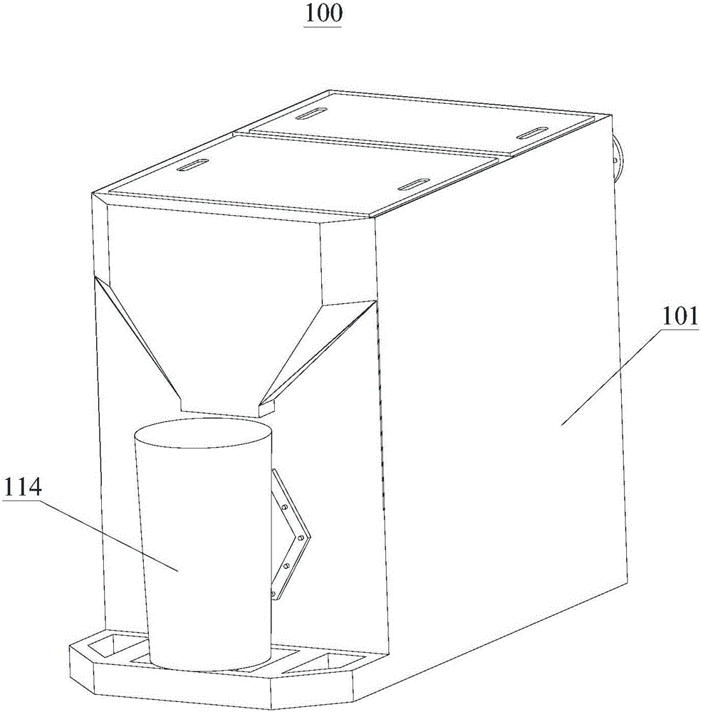
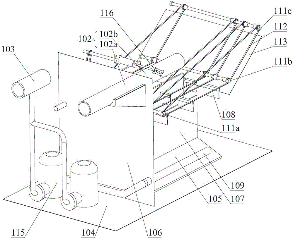
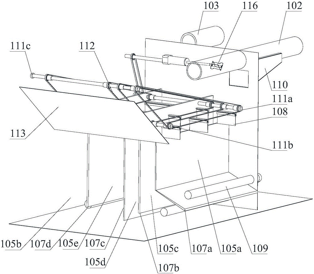
Integrated oil-water separation oil removal equipment

A technology of oil-water separation and oil separation, applied in the direction of liquid separation, separation method, grease/oily substance/floating matter removal device, etc., can solve the problems of high construction cost, inability to separate food residues, incomplete treatment of catering wastewater, etc., to achieve Effects of reducing pollution and waste of resources, easy promotion and use, and convenient lightweight treatment

Active Publication Date: 2016-06-22
中科沃德利华(北京)生态环保科技有限公司
View PDF6 Cites 1 Cited by
  • Summary
  • Abstract
  • Description
  • Claims
  • Application Information

AI Technical Summary

Problems solved by technology

However, the structure and structure of the current sewage treatment system is very complicated, the construction cost is very high, and it is difficult to promote. Moreover, this sewage treatment system can only separate the grease in the catering wastewater, and cannot directly separate the food residue in the catering wastewater. It is also necessary to collect and treat the food residues in the catering wastewater. Therefore, this sewage treatment system does not completely treat the catering wastewater, and it is inconvenient to use.

Method used


Image

  • Integrated oil-water separation oil removal equipment
  • Integrated oil-water separation oil removal equipment
  • Integrated oil-water separation oil removal equipment

Examples


Embodiment Construction

[0027] In order to make the purpose, technical solutions and advantages of the embodiments of the present invention clearer, the technical solutions in the embodiments of the present invention will be clearly and completely described below in conjunction with the drawings in the embodiments of the present invention. Obviously, the described embodiments It is a part of embodiments of the present invention, but not all embodiments. The components of the embodiments of the invention generally described and illustrated in the figures herein may be arranged and designed in a variety of different configurations.

[0028] Accordingly, the following detailed description of the embodiments of the invention provided in the accompanying drawings is not intended to limit the scope of the claimed invention, but merely represents selected embodiments of the invention. Based on the embodiments of the present invention, all other embodiments obtained by persons of ordinary skill in the art wi...


PUM


Abstract

The invention provides integrated oil-water separation oil removal equipment, and relates to the technical field of wastewater treatment. The oil-water separation oil removal equipment comprises a shell, a water inlet tube and a water outlet tube, wherein the water inlet tube and the water outlet tube are respectively communicated with the inside of the shell; a first partition is arranged in the shell and divides the inside of the shell into a water purifying cavity and a separating cavity; a plurality of second partitions which are arranged at intervals are arranged in the separating cavity; the separating cavity is divided into a plurality of secondary separating cavities which are arrayed in parallel by the second partitions; tops and bottoms of the secondary separating cavities are successively communicated with one another in a staggered manner to form a snakelike water circulating channel; the secondary separating cavities positioned at the head and the tail are a water inlet cavity and a water outlet cavity respectively; the water inlet cavity is communicated with the water inlet tube; the water outlet cavity is communicated with the water purifying cavity; and the water purifying cavity is communicated with the water outlet tube. By the integrated oil-water separation oil removal equipment, sundries such as fat and food residues in restaurant waste water can be separated, the restaurant waste water is separated preliminarily, follow-up lightweight treatment of the restaurant waste water is facilitated, and pollution and resource waste to an environment are reduced. The integrated oil-water separation oil removal equipment is simple in structure and easy to popularize and use.

Description

technical field [0001] The invention relates to the technical field of waste water treatment, in particular to an integrated oil-water separation and oil separation device. Background technique [0002] With the development of the economy, people eat out more and more times, and the development of the catering industry is also more and more prosperous. A restaurant or restaurant in normal operation produces a large amount of catering wastewater containing food residues every year. It is usually not recommended to discharge these catering wastewater directly into the sewer, because the catering wastewater contains food residues, which will breed bacteria after being discharged directly into the sewer , providing living conditions for rats and other pests, seriously polluting the environment. Moreover, catering wastewater contains a lot of oil, especially the catering wastewater produced by Chinese restaurants will contain a lot of oil, directly discharged into the sewer will...

Claims


Application Information

Patent Timeline
IPC IPC(8): C02F1/40
CPCC02F1/40
Inventor 於璨鹏
Owner 中科沃德利华(北京)生态环保科技有限公司
Learn More