Supercharge Your Innovation With Domain-Expert AI Agents!

Full hydraulic rock tunnel drilling device

A fully hydraulic and support device technology, which is applied in the field of drilling devices and fully hydraulic rock tunnel drilling devices, can solve the problems of tree disturbance, waste of resources, and large occupied area, so as to achieve full utilization, improve construction efficiency, and improve economic benefits Effect

Inactive Publication Date: 2016-06-22
NANJING HAIJIE MACHINERY MFG CO LTD +1
View PDF7 Cites 3 Cited by
  • Summary
  • Abstract
  • Description
  • Claims
  • Application Information

AI Technical Summary

Problems solved by technology

In addition, it is very easy to cause disturbance to surrounding rocks, underground facilities and trees
The shield tunneling method is a construction method for cutting rock mass, conveying rock ballast, and assembling tunnel lining. The construction area is relatively large, the cost of shield tunneling equipment is high, and the life of cutting tools and seals is short. Due to defects in construction principles, cutting rock The body cannot be used for secondary use, resulting in a huge waste of resources
In addition, environmental factors sometimes become the decisive factor in choosing a construction method. However, in the environment where the site plane of the hole is narrow and it is impossible to assemble large-scale roadheaders, the construction of large-scale roadheaders is limited. There is no suitable construction device that can carry out drilling according to construction needs. hole

Method used


Image

  • Full hydraulic rock tunnel drilling device
  • Full hydraulic rock tunnel drilling device
  • Full hydraulic rock tunnel drilling device

Examples


Embodiment

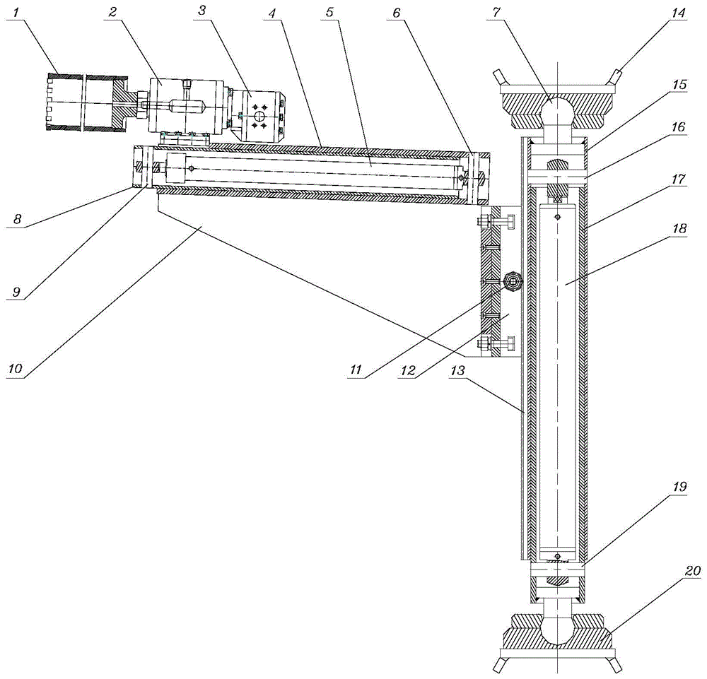
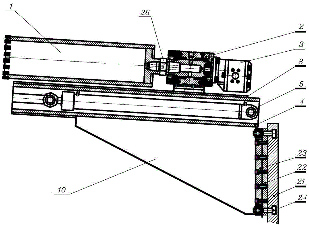
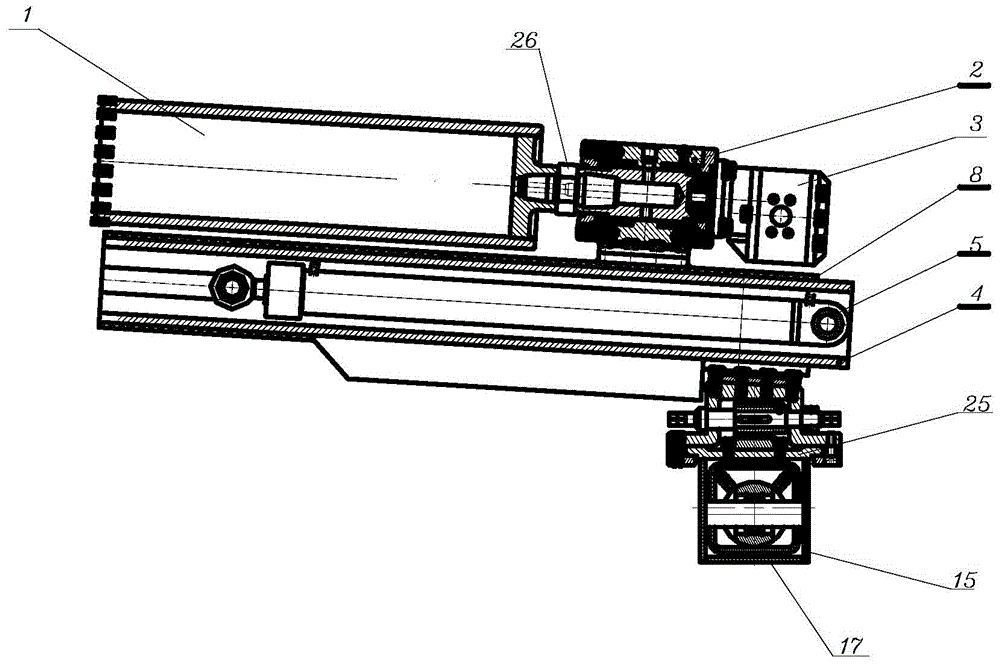
[0019] The structure of this embodiment is as Figure 1 to Figure 3 As shown, a drilling and rock splitting device includes a supporting device, the supporting device includes a strut fixed sleeve 17 containing a strut cylinder 18, the strut fixed sleeve 17 is externally connected with a strut movable sleeve 15, and the strut cylinder 18 passes through the The strut fixed sleeve hinge shaft 19 and the strut movable sleeve hinge shaft 16 connect the strut fixed sleeve 17 and the strut movable sleeve 15, and the two ends of the strut extend outward until the center of the support base 20, and the extended ends of the strut form a brace. The rod head 7 is connected with the depression in the center of the support base 20, and the design of the ball head is convenient for adjusting the support angle, so that the support is more stable. The supporting base 20 has a three-layer structure, and the layer width increases layer by layer from top to bottom. The lower end of the base is p...


PUM


Abstract

The invention relates to a hole drilling device, in particular to a full hydraulic rock tunnel drilling device, and belongs to the technical field of tunnel construction equipment. The full hydraulic rock tunnel drilling device structurally comprises a support device, wherein the support device comprises a support rod fixed sleeve; a support rod oil cylinder is arranged in the support rod fixed sleeve; a support rod movable sleeve is connected outside the support rod fixed sleeve in a sleeving way; a profiling guide rail is in transmission connection onto the support rod movable sleeve; support bases are fixed at two ends of a support rod; the profiling guide rail consists of a T-shaped groove profiling base, a movable bottom plate and a fixing seat; the movable bottom plate is arranged on the T-shaped groove profiling base; the fixing seat is fixedly connected with the movable bottom plate; the fixing seat is connected with one side of a triangular reinforcing rib plate; a feeding device is fixed on the triangular reinforcing rib plate and one side adjacent to the connecting side of the fixing seat; the feeding deice comprises a feeding fixed sleeve; a feeding oil cylinder is arranged in the feeding fixed sleeve; a feeding movable sleeve is connected outside the feeding fixed sleeve in a sleeving way; a rock core drilling tool assembly is fixed on the upper surface of the feeding movable sleeve; and the rock core drilling tool assembly is sequentially provided with a rock core drill bit, a transmission mechanism and a hydraulic motor from the front side to the back side. The full hydraulic rock tunnel drilling device has the advantages that the efficiency of a method is high; the design of the device is reasonable; and the operation is safe and reliable.

Description

technical field [0001] The invention relates to a drilling device, in particular to a fully hydraulic rock tunnel drilling device, which belongs to the technical field of tunnel construction equipment. Background technique [0002] With the development of society, the development of various large-scale projects, the expansion of various large-scale construction projects, the rapid development of construction projects such as railways, light rail, highways, and water diversion projects, the expansion of city scale, the lack of land and other resources, to the subway The development has brought new leap heights. Therefore, the development of tunnel and chamber engineering is inevitable. At present, such projects mainly adopt mining method and shield method. The mining method is the blasting method, which is mainly completed by drilling and blasting methods, supplemented by slag removal by shipping machinery. The blasting, lining, support, ventilation, dust prevention, gas p...

Claims


Application Information

Patent Timeline
Patent Type & Authority Applications(China)
IPC IPC(8): E21D9/10
CPCE21C37/04E21D9/00E21D9/10E21D9/1053
Inventor 施杰严道友严尚云施洋孙蓉
Owner NANJING HAIJIE MACHINERY MFG CO LTD
Features
  • R&D
  • Intellectual Property
  • Life Sciences
  • Materials
  • Tech Scout
  • Unparalleled Data Quality
  • Higher Quality Content
  • 60% Fewer Hallucinations
Learn More