
Jet type flow detection device for medical instrument

A technology of flow detection device and medical instrument, which is applied in the direction of detecting fluid flow by measuring differential pressure, volume/mass flow generated by mechanical effect, etc., to achieve the effect of suppressing large error of flow signal, increasing stability and satisfying accuracy

Active Publication Date: 2016-06-22
JIANGSU YUYUE MEDICAL EQUIP&SUPPLY CO LTD +3
View PDF5 Cites 2 Cited by
  • Summary
  • Abstract
  • Description
  • Claims
  • Application Information

AI Technical Summary

Problems solved by technology

Although the bidirectional flow V-cone flowmeter seems to realize bidirectional measurement, it still needs to be switched to achieve it, and is not suitable for ventilators and anesthesia machines that need to use flow detection to judge respiratory and respiratory events. Moreover, the bidirectional The flow V-cone flowmeter is also only suitable for occasions with a pipe diameter of 50mm or more, and it is not suitable for small occasions such as medical instruments that require high measurement accuracy.

Method used


Image

  • Jet type flow detection device for medical instrument
  • Jet type flow detection device for medical instrument
  • Jet type flow detection device for medical instrument

Examples


Embodiment 1

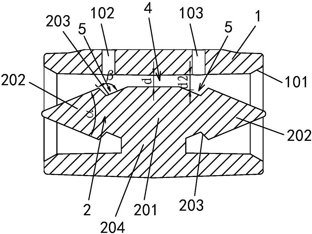
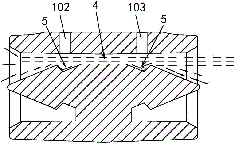
[0025] Embodiment one: see figure 1 and figure 2 Shown:

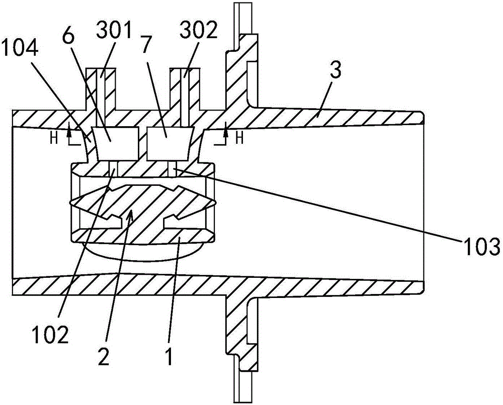
[0026] A spray flow detection device for medical instruments comprises a straight pipe body 1 and a spray body 2 arranged in the straight pipe body 1 .

[0027] see figure 1 As shown, the straight pipe body 1 is arranged along the fluid flow direction, and the spray body 2 includes a straight-segment-shaped middle part 201 and spray cones 202 located at both ends of the straight-segment-shaped middle part 201 in the fluid flow direction. Front and rear symmetry in the flow direction, the apex angle α of the spray cone 202 is 10°-50°, preferably 20-50°, and the best example is 22.5° or 45° 。 The injection body 2 is supported and connected to the inner wall of the straight pipe body 1 by one or more support ribs 204 . When there are multiple support ribs 204 , the plurality of support ribs 204 are evenly distributed in the circumferential direction of the straight pipe body 1 .

[0028] see figure 1 As shown, the ...

Embodiment 3

[0041] Embodiment three: see Figure 8 Shown:

[0042] A spray flow detection device for medical instruments comprises a straight pipe body 1 and a spray body 2 arranged in the straight pipe body 1 . The difference from the second embodiment is that a through hole 205 is opened in the center of the jet body 2 along the fluid flow direction as a flow channel, so that besides the flow channels on the periphery of the jet body, a flow channel is also added in the center of the jet body. The number of the through holes 205 is not limited, and may be multiple.


PUM


Abstract

A jet type flow detection device for a medical instrument is characterized in that the device comprises a straight pipe (1) and a jet body (2) arranged in the straight pipe (1); the straight pipe (1) is arranged in the flowing direction of fluid; the jet body (2) comprises a straight section middle part (201) and jet cones (202) located at the two ends of the straight section middle part (201) in the flowing direction of the fluid, the two jet cones (202) are symmetrically arranged in a front-back mode in the flowing direction of the fluid, and the cone apex angle alpha of each jet cone (202) is 10-50 degrees; an air flow gathering and compressing area (4) is formed between the inner wall of the straight pipe (1) and the straight section middle part (201) of the jet body (2); an upstream pressure tapping (102) is formed in the position, corresponding to the cone bottom of one jet cone (202), on the straight pipe (1); a downstream pressure tapping (103) is formed in the position, corresponding to the cone bottom of the other jet cone, on the straight pipe (1).The jet type flow detection device meets the requirements of the medical instrument for high precision, small errors and miniaturization of flow detection devices.

Description

technical field [0001] The present invention relates to the field of medical equipment, in particular to a jet-type flow detection device for medical instruments. The medical equipment refers to instruments such as ventilators, oxygen generators, and anesthesia machines that require flow detection. Background technique [0002] At present, the measurement laminar flow structure of the most used flow detection devices on the market adopts V cone, Venturi, orifice plate, etc., and the pressure is measured by measuring the pressure at both ends of the laminar flow structure before and after throttling. If the value is poor, the flow value passing through the pipeline is calculated, and the adjustment of the accuracy value depends on the size of the throttle area to determine the accuracy of the value. It has the advantages of good long-term stability and good repeatability, but the V-cone has its fatal flaws. Irreversible measurement, and the Venturi structure needs to occupy a...

Claims


Application Information

Patent Timeline
IPC IPC(8): G01F1/36G01F1/40
CPCG01F1/36G01F1/40
Inventor 杜文芝朱晶张宏圣郭建明
Owner JIANGSU YUYUE MEDICAL EQUIP&SUPPLY CO LTD
Learn More