

Metallographic specimen clamping device
A clamping device and metallographic sample technology, applied in the preparation of test samples, grinding workpiece supports, etc., can solve problems such as uneven edges, inconvenient clamping, and chamfering, and achieve low production costs and easy operation. Convenience, easy disassembly and assembly
- Summary
- Abstract
- Description
- Claims
- Application Information
AI Technical Summary
Problems solved by technology
Method used
Image

Examples
Embodiment 1
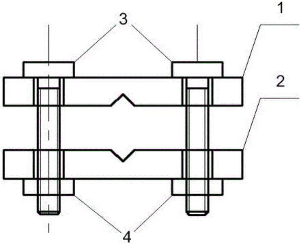
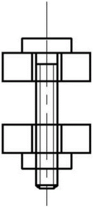
[0018] Such as Figures 1 to 6 As shown, the metallographic sample clamping device of this embodiment includes: an upper clamp 1 and a lower clamp 2, and the clamping surfaces of the upper clamp and the lower clamp are provided with anti-slip protrusion structures. The corresponding positions on the upper and lower clamps are respectively provided with two through holes, and the two through holes on the upper and lower clamps are arranged symmetrically; the studs 3 pass through the upper and lower clamps. The through holes at the corresponding positions are provided with nuts 4 on the studs. The corresponding positions on the clamping surfaces of the upper clamp and the lower clamp are respectively provided with a V-shaped notch groove. The V-shaped notch grooves on the upper and lower clamps are arranged between the two through holes.
[0019] In this embodiment, the upper fixture 1 is a rectangular parallelepiped aluminum plate with two through holes, the through holes are...
Embodiment 2
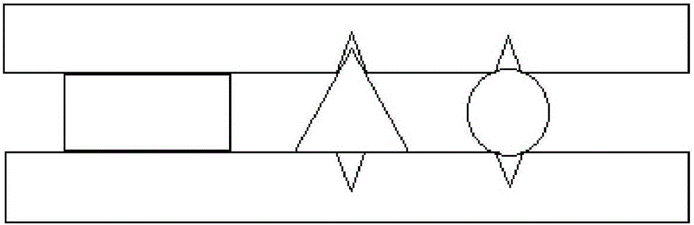
[0023] Such as figure 2 As shown, the metallographic sample clamping device of this embodiment differs from that of Embodiment 1 in that: the clamping surfaces of the upper clamp and the lower clamp are respectively provided with two V-shaped notch grooves, The V-shaped notch grooves on the upper fixture and the lower fixture are in one-to-one correspondence, and the V-shaped notch grooves at the corresponding positions have the same structure, and the two V-shaped grooves on the upper fixture have different sizes. The dimensions of the two V-grooves are different.
[0024] The other structures of this embodiment are the same as those of Embodiment 1, and the method of use is also the same, which will not be repeated here. In this embodiment, the upper and lower clamps are respectively provided with two V-shaped notch grooves of different sizes, which can meet the use of samples of different structures, and are more convenient to use, convenient to clamp multiple irregular s...
Embodiment 3
[0026] The metallographic sample clamping device of this embodiment includes: an upper clamp and a lower clamp, and the clamping surfaces of the upper clamp and the lower clamp are provided with anti-slip protrusion structures. The corresponding positions on the upper and lower clamps are respectively provided with four through holes, and the four through holes on the upper and lower clamps are arranged symmetrically; the studs pass through the upper and lower clamps on the corresponding The through hole at the position, the nut is provided on the stud. Two V-shaped notch grooves are respectively provided at corresponding positions on the clamping surfaces of the upper clamp and the lower clamp. The V-shaped notch grooves on the upper and lower clamps are respectively arranged between two adjacent through holes. In this embodiment, the sizes of the two V-shaped grooves on the upper fixture are different, and the sizes of the two V-shaped grooves on the lower fixture are also ...
PUM
 Abstract
Description
Claims
Application Information