Three-dimensional physical model test method
A model test and three-dimensional physics technology, which is applied in the field of three-dimensional physical model test, can solve the problems of difficult simulation and realization of the test model, and achieve the effect of realistic simulation effect and appropriate inclination angle
- Summary
- Abstract
- Description
- Claims
- Application Information
AI Technical Summary
Problems solved by technology
Method used
Image
Examples
Embodiment 1
[0068] Example 1: Roadway Excavation Simulation
[0069] The method for simulating roadway excavation by using the above-mentioned three-dimensional physical model test device comprises the following steps:
[0070] Step 1: Construct the reaction frame A0 and build the model device:
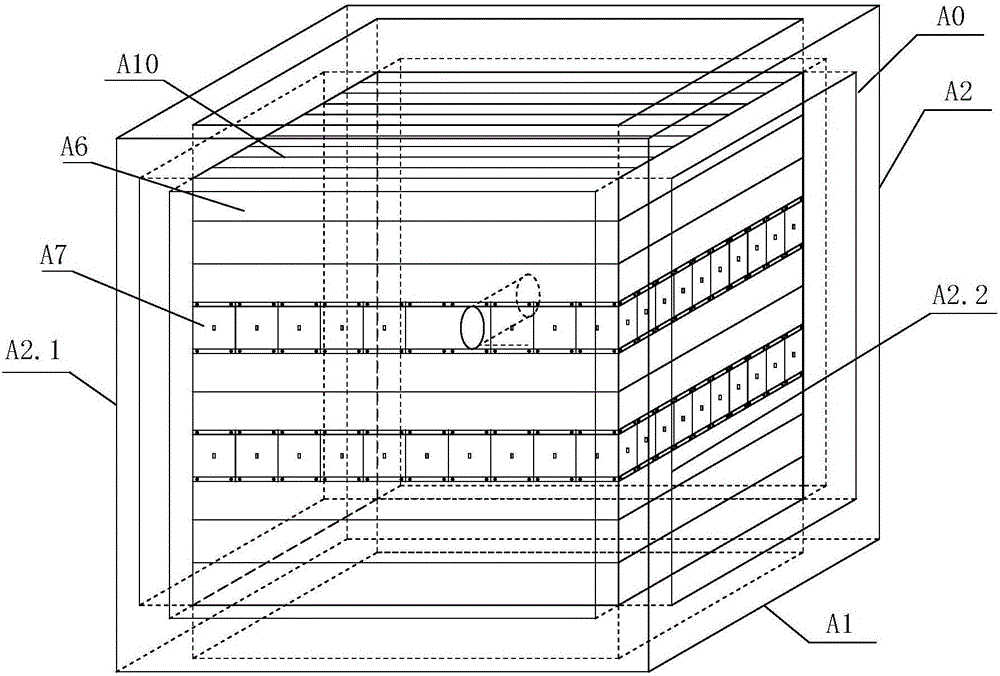
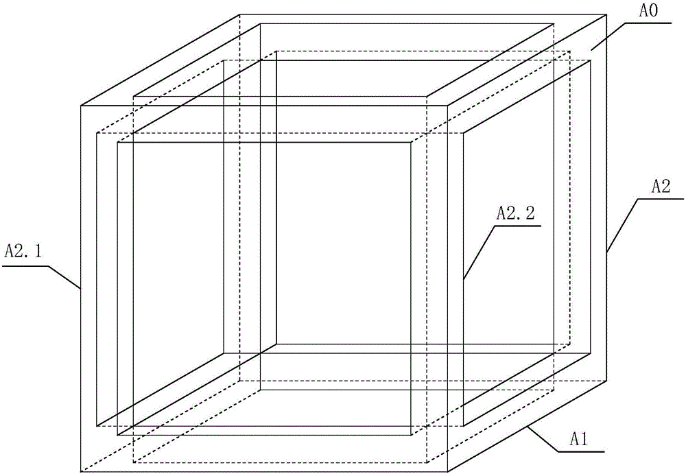
[0071] To construct the reaction force frame A0, a plurality of parallel rectangular large steel plates A6 with a horizontal plane angle α are arranged on the cubic frame surface A11, and a plurality of parallel rectangular small steel plates A7 are arranged between two rectangular large steel plates A6.
[0072] A rock mass model A12 is set in the reaction frame A0, and a vertical loading system A15, a horizontal front-back loading system A14, and a horizontal left-right loading system A13 are installed.
[0073] Set the vertical loading system A15, the horizontal front-back loading system A14, and the horizontal left-right loading system A13 to load pressure on the rock mass model A12.
[007...
Embodiment 2
[0083] Example 2: Simulation of coal seam horizontal and inclined mining
[0084] The method for simulating horizontal coal seam mining by using the above-mentioned three-dimensional physical model test device comprises the following steps:
[0085] Steps 1-3: Consistent with the simulated roadway excavation in Embodiment 1. Until the excavation of the first roadway is completed.
[0086] Step 4: Remove the next small rectangular steel plate A7 adjacent to the removed first small rectangular steel plate A7.
[0087] Step 5: Repeat steps 2 to 4 to complete the working face advancement simulation.
[0088] In this embodiment, the adjacent small rectangular steel plates A7 are sequentially removed, so that a full recovery simulation can be performed on a simulated working face between two large rectangular steel plates A6 on the cube frame surface A11.
[0089] If necessary, the above steps can be repeated for another row of rectangular small steel plates A7 between the other ...
Embodiment 3
[0091] Embodiment 3: mining simulation of metal ore caving method
[0092] Steps 1-4: Consistent with the simulated roadway excavation in Embodiment 1; until the excavation of the first roadway is completed. The following steps are then taken to simulate metal ore caving mining production:
[0093] Step 5: Manipulate the vertical loading system A15, the horizontal front-back loading system A14, and the horizontal left-right loading system A13, control and generate vibration, and simulate an on-site blasting of a working face.
[0094] The jacks that control each loading system cooperate with each other to simulate an on-site blasting, which is the "ore falling" in actual production.
[0095] Step 6: directly discharge the rock mass model A12 fragments formed by the vibration.
[0096] The rock mass model A12 fragments formed by the vibration are the "ores" that have collapsed in the simulation of actual production; after the "ores" are discharged, this simulation is completed,...
PUM
 Abstract
Description
Claims
Application Information
 - R&D
- Intellectual Property
- Life Sciences
- Materials
- Tech Scout
- Unparalleled Data Quality
- Higher Quality Content
- 60% Fewer Hallucinations
Browse by: Latest US Patents, China's latest patents, Technical Efficacy Thesaurus, Application Domain, Technology Topic, Popular Technical Reports.
© 2025 PatSnap. All rights reserved.Legal|Privacy policy|Modern Slavery Act Transparency Statement|Sitemap|About US| Contact US: help@patsnap.com


