Three-phase power grid electrical parameter measurement method and intelligent circuit breaker control method

A technology of three-phase power grid and measurement method, which is applied in the direction of electric power measurement through current/voltage, measurement with digital measurement technology, and measurement device, which can solve the problems of long measurement period, slow calculation speed, and large calculation amount, and achieve Simplify the switching strategy, improve the switching accuracy, and solve the effect of diagnosis and alarm

Inactive Publication Date: 2016-06-22
XIAMEN UNIV OF TECH
9 Cites 2 Cited by

AI-Extracted Technical Summary

Problems solved by technology

However, its electrical parameter measurement method is complicated, the calculation amount is large, the calculation speed is slow, and the measurement period is long, which affects th...

Method used

In sum, the present invention adopts Fast Fourier to carry out the calculation and measurement of three-phase power grid electric parameters and adopts Profibus bus line to carry out remote communication monitoring, can effectively improve switching precision, simplifies switching strategy, has solved intelligent circuit breaker diagnosis The problems of alarm and high-speed real-time data communication have greatly improved the overall performance of the circuit breaker, and can realize the "four remote" functions of telemetry, remote control, remote communication, and remote adjustment of the on-site circuit breaker.
The present invention also discloses a control method for an intelligent circuit breaker, including obtaining each phase (1≤K≤N/2-1) harmonic of each phase of the three-phase power grid by using the above-mentioned three-phase power grid electrical parameter measurement method The effective value (UK, IK) and active power (PK) of voltage and current are compared with the setting value preset in the smart circuit breaker, and the control i...

Abstract

The invention relates to the field of intelligent circuit breaker control, and discloses a three-phase power grid electrical parameter measurement method comprising the following steps that A1, current and voltage signals of all phases of a three-phase power grid are synchronously sampled; A2, the sampled current and voltage signals of all phases are conditioned and converted into digital signals through A/D conversion; and A3, the converted current and voltage of all phases are calculated by adopting fast Fourier transform so that effective values UK and IK of harmonic voltage and current of each order and active power PK of all phases are obtained. The invention also discloses an intelligent circuit breaker control method. Intelligent circuit breaker control is performed by adopting the method so that switching precision can be effectively enhanced, the switching strategy can be simplified, the problems of intelligent circuit breaker diagnosis alarm and high-speed real-time data communication can be solved, the overall performance of the circuit breaker can be greatly enhanced, and the "four remote" functions of remote metering, remote control, remote signaling and remote regulating of the onsite circuit breaker can be realized.

Application Domain

Effective value measurementsPower measurement by current/voltage +2

Technology Topic

Fft fast fourier transformPower grid +10

Image

  • Three-phase power grid electrical parameter measurement method and intelligent circuit breaker control method
  • Three-phase power grid electrical parameter measurement method and intelligent circuit breaker control method
  • Three-phase power grid electrical parameter measurement method and intelligent circuit breaker control method

Examples

  • Experimental program(1)

Example Embodiment

[0023] The present invention will now be further described with reference to the drawings and specific embodiments.
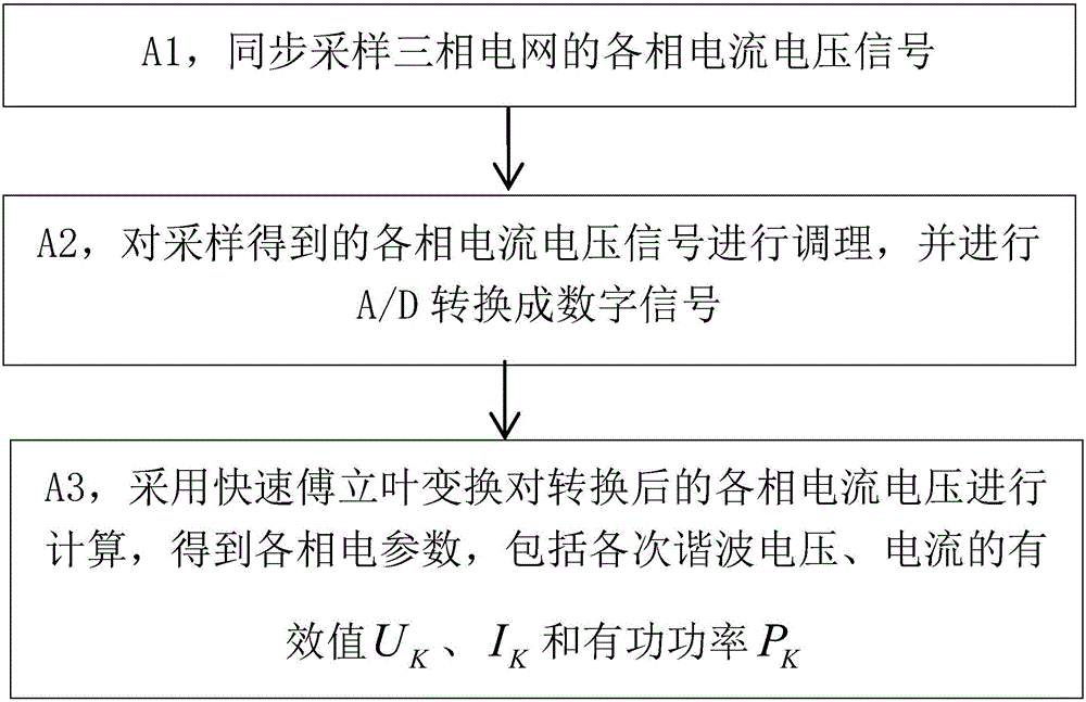
[0024] Such as figure 1 As shown, the three-phase grid electrical parameter measurement method includes the following steps
[0025] A1, synchronously sampling the current and voltage of each phase of the three-phase power grid.
[0026] Specifically, a high-precision air-core transformer is used to sample the current signal, and a voltage divider circuit is used to sample the voltage signal. Fourier transform is based on synchronous sampling. It requires the entire cycle to intercept the signal and sample at strict equal intervals. Therefore, it is necessary to ensure that the sampling signal and the actual signal are strictly synchronized, that is, the sampling frequency is an integer multiple of the signal frequency, otherwise it will appear Spectrum leakage causes errors in the Fourier transform results and affects measurement accuracy. Therefore, the sampling frequency needs to be adjusted in real time according to the changes of the three-phase grid frequency. The specific method is:
[0027] First measure the power grid period T, and then determine the timing value T/N of the timer according to the period T and the number of sampling points N in each period, that is, the software synchronization mode is realized by the timer interrupt. First, the power frequency voltage of the three-phase power grid is formed into a square wave, and the CPU captures and judges the rising or falling edge of the square wave in an external interrupt mode. At the same time, the time difference between the two jumps is calculated to calculate the power frequency cycle in real time. Calculate the next sampling interval T through the real-time power frequency cycle S , And then adjust the sampling timer period register value, adjust the interrupt time, complete synchronous sampling, and realize software phase lock. Even if the frequency of the three-phase power grid fluctuates, it can ensure that 256 sampling values ​​are accurately obtained in one cycle. The influence of changing system frequency on the measurement accuracy is reduced, and the measurement accuracy is improved.
[0028] A2, conditioning the current and voltage signals of each phase obtained by sampling, and A/D conversion into digital signals.
[0029] Specifically, the current and voltage signals of each phase sampled in step A1 are adjusted by the conditioning circuit, and then converted into digital signals by A/D. Regarding signal conditioning and A/D conversion, reference may be made to the prior art, which will not be elaborated here.
[0030] A3, using fast Fourier transform to calculate the current and voltage of each phase converted in step A2 to obtain the electrical parameters of each phase, including the effective value U of each harmonic voltage and current K , I K And active power P K
[0031] Fast Fourier Transform (FFT) is a fast algorithm for Discrete Fourier Transform (DFT), which uses the twiddle factor W N =e -j2π/N Due to its periodicity and symmetry, the calculation of DFT is successively decomposed into smaller DFTs. For the point sequence x(n), its DFT is defined as:
[0032] X ( k ) = X n = 0 n - 1 x ( n ) W N n k k = 0 , 1 , ... , N - 1 - - - ( 1 )
[0033] In the above formula, let N=2 M , M is a positive integer, and x(n) can be grouped by parity, that is, let n=2r and n=2r+1, where r=0,1,...N/2-1, you can get
[0034] x ( n ) = X r = 0 N / 2 - 1 x ( 2 r ) + X r = 0 N / 2 - 1 x ( 2 r + 1 ) - - - ( 2 )
[0035] Using the periodicity and symmetry of the twiddle factor to sort out equations (1) and (2),
[0036] X ( k ) = A ( k ) + W N k B ( k ) k = 0 , 1 , ... , N / 2 - 1 - - - ( 3 )
[0037] X ( k + N / 2 ) = A ( k ) - W N k B ( k ) k = 0 , 1 , ... , N / 2 - 1 - - - ( 4 )
[0038] among them For A(k), B(k) continue to be decomposed by the above method until the two-point DFT. The above algorithm separates time by parity, so it is called time extraction algorithm.
[0039] In the process of real-time detection and processing of three-phase power grid parameters using FFT, three-phase voltage and three-phase current need to be sampled simultaneously. The measurement algorithm for any phase voltage and current is as follows: Simultaneously sample N-point voltage sequence {u(n)} and current sequence {i(n)}, and the two form a complex discrete time sequence:
[0040] x(n)=u(n)+ji(n), 0≤n≤N-1(5)
[0041] For the complex sequence {x(n)}, the discrete Fourier transform (DFT) is:
[0042] X ( K ) = D F T [ x ( n ) ] = X n = 0 N - 1 [ x ( n ) e - j ( 2 π / N ) n K ] - - - ( 6 )
[0043] From equation (4)
[0044] u ( n ) = 1 2 [ x ( n ) + x * ( n ) ] i ( n ) = 1 2 j [ x ( n ) - x * ( n ) ] - - - ( 7 )
[0045] Carry on DFT transformation to formula (6), and by its complex conjugate nature, the frequency spectrum of voltage and current can be obtained as:
[0046] U ( K ) = 1 2 [ X ( K ) + X * ( N - K ) ] I ( K ) = 1 2 [ X ( K ) - X * ( N - K ) ] - - - ( 8 )
[0047] Where: X(K) and X * (N-K) are x(n) and x respectively * (n) DFT transform. In the process of processing data, first perform FFT transformation on formula (5) to obtain X(K), and then obtain X * (N-K), finally use the transformation method of (8) to get the frequency spectrum of voltage and current. Assume Is the vector representation of U(t) the Kth harmonic; Is the vector representation of the Kth harmonic of i(t), the voltage, current vector and its spectrum have the following relationship:
[0048] U K · = 2 2 N U ( K ) I K · = 2 2 N I ( K ) - - - ( 9 )
[0049] When K=0, X(NK)=X(N)=X(0), implying periodicity, and the DC component is not considered here. In this way, each time of this phase (1≤K≤N/2- 1) The effective value of harmonic voltage and current (U K , I K ) And active power (P K )for:
[0050] U K = 1 2 N · [ X R ( K ) + X R ( N - K ) ] 2 + [ X 1 ( K ) - X 1 ( N - K ) ] 2 - - - ( 10 )
[0051] I K = 1 2 N · [ X R ( K ) + X R ( N - K ) ] 2 + [ X 1 ( K ) - X 1 ( N - K ) ] 2 - - - ( 11 )
[0052] P K = 1 N 2 [ X R ( R ) X 1 ( N - K ) + X 1 ( K ) X R ( N - K ) ] - - - ( 12 )
[0053] Where: X R (K) and X 1 (K) are the real and imaginary parts of X(K), X R (N-K) and X 1 (N-K) are the real and imaginary parts of X(N-K), respectively.
[0054] Obtain the effective value of each phase (1≤K≤N/2-1) harmonic voltage and current (U K , I K ) And active power (P K ), it can be compared with the setting value preset in the smart circuit breaker to perform corresponding protection actions to protect the safety of the entire power grid and electrical equipment.
[0055] The invention also discloses a control method of a smart circuit breaker, which includes using the above-mentioned three-phase power grid electrical parameter measurement method to obtain the harmonic voltages and currents of each phase of the three-phase power grid (1≤K≤N/2-1) The effective value (U K , I K ) And active power (P K ), after comparing it with the setting value preset in the smart circuit breaker, output control information that meets the preset protection characteristics, and control the smart circuit breaker to perform corresponding protection actions, such as short circuit, overvoltage, etc., control the smart circuit breaker The switch is opened to protect the safety of the entire power grid and electrical equipment. At the same time, it communicates with the remote master station (such as host computer, PLC, etc.) through the Profibus bus, and transfers the measured data (including the harmonic voltage of each phase of the three-phase power grid (1≤K≤N/2-1), The effective value of current (U K , I K ) And active power (P K ) And three-phase voltage, current waveforms, etc.) and the state of the circuit breaker (such as open or closed, in the test position, ready to close), setting value parameters, and fault information are converted into Profibus protocol format and sent to the remote master station for analysis and processing And display for monitoring, and set the status and setting value of the circuit breaker through the remote master station according to the operating conditions for remote control operation.
[0056] figure 2 with image 3 The control system and the intelligent controller in the intelligent circuit breaker used to realize the above-mentioned intelligent circuit breaker control method are given.
[0057] To sum up, the present invention adopts fast Fourier for calculation and measurement of three-phase grid electrical parameters and Profibus for remote communication monitoring, which can effectively improve switching accuracy, simplify switching strategies, and solve intelligent circuit breaker diagnosis and alarm, high speed The difficulty of real-time data communication greatly improves the overall performance of the circuit breaker, and can realize the "four remote" functions of remote measurement, remote control, remote communication, and remote adjustment of the on-site circuit breaker.
[0058] Although the present invention has been specifically shown and described in conjunction with the preferred embodiments, those skilled in the art should understand that the present invention can be modified in form and detail without departing from the spirit and scope of the present invention as defined by the appended claims. Various changes are within the protection scope of the present invention.

PUM

no PUM

Description & Claims & Application Information

We can also present the details of the Description, Claims and Application information to help users get a comprehensive understanding of the technical details of the patent, such as background art, summary of invention, brief description of drawings, description of embodiments, and other original content. On the other hand, users can also determine the specific scope of protection of the technology through the list of claims; as well as understand the changes in the life cycle of the technology with the presentation of the patent timeline. Login to view more.

Similar technology patents

Method and apparatus for implementing resource scheduling

ActiveCN101488908AImprove business feelimprove overall performance
Owner:HUAWEI TECH CO LTD

Silk-screen printing method for positive electrode of solar battery

ActiveCN102689534AAvoid electrical performance degradationimprove overall performance
Owner:JETION SOLAR HLDG
Why Eureka
Try Eureka