Image processing method and electronic equipment

An electronic device and image processing technology, applied in the field of image processing, can solve problems such as deformation of portraits and affecting user experience, and achieve the effect of avoiding severe distortion

Active Publication Date: 2016-06-22
LENOVO (BEIJING) LTD
View PDF5 Cites 2 Cited by
  • Summary
  • Abstract
  • Description
  • Claims
  • Application Information

AI Technical Summary

Problems solved by technology

The angle of view of the lower camera changes from an almost horizontal normal angle of view to an upward angle of view from the bottom up, resulting in local deformation of the collected portraits, such as protruding big noses and double chins, and the head looks backward, etc. Seriously affect user experience

Method used


Image

  • Image processing method and electronic equipment
  • Image processing method and electronic equipment
  • Image processing method and electronic equipment

Examples


Embodiment 1

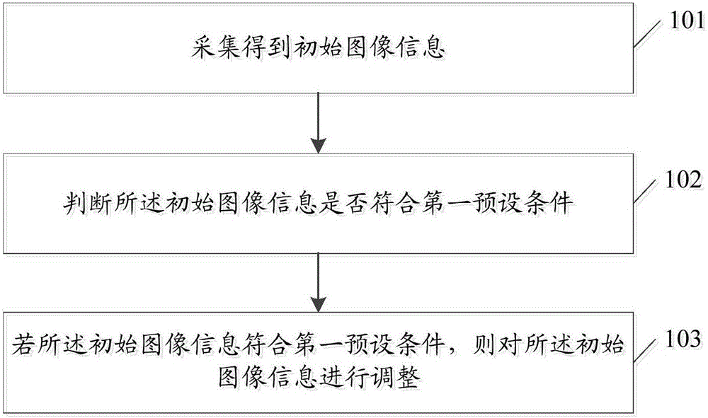
[0049] figure 1 It is a schematic flow chart of the image processing method in Embodiment 1 of the present invention. The image processing method in this example is applied to electronic equipment, such as figure 1 As shown, the image processing method includes the following steps:

[0050] Step 101, acquiring initial image information;

[0051] Here, the initial image information includes at least target object image information.

[0052] Specifically, when the electronic device scans and determines that a target object currently falls within the range of the image collection area, the initial image information may be collected by the collection unit in the electronic device. The collection unit may be a bottom camera in the electronic device.

[0053] Wherein, the image information of the target object is usually face image information; correspondingly, the initial image information is image information including at least a face image.

[0054] Step 102, judging whether ...

Embodiment 2

[0063] image 3 It is a schematic flow chart of the image processing method in Embodiment 2 of the present invention. The image processing method in this example is applied to electronic equipment, such as image 3 As shown, the image processing method includes the following steps:

[0064] Step 101, acquiring initial image information;

[0065] Here, the initial image information includes at least target object image information.

[0066] Specifically, when the electronic device scans and determines that a target object currently falls within the range of the image collection area, the initial image information may be collected by the collection unit in the electronic device. The collection unit may be a bottom camera in the electronic device.

[0067] Wherein, the image information of the target object is usually face image information; correspondingly, the initial image information is image information including at least a face image.

[0068] Step 1021, perform brightn...

Embodiment 3

[0079] Figure 4 It is a schematic flow chart of the image processing method in Embodiment 3 of the present invention. The image processing method in this example is applied to electronic equipment, such as Figure 4 As shown, the image processing method includes the following steps:

[0080] Step 101, acquiring initial image information;

[0081] Here, the initial image information includes at least target object image information.

[0082] Specifically, when the electronic device scans and determines that a target object currently falls within the range of the image collection area, the initial image information may be collected by the collection unit in the electronic device. The collection unit may be a bottom camera in the electronic device.

[0083] Wherein, the image information of the target object is usually face image information; correspondingly, the initial image information is image information including at least a face image.

[0084] Step 102, judging whethe...


PUM


Abstract

The invention discloses an image processing method and electronic equipment. The method comprises: collection is carried out to obtain initial image information at least including target object image information; whether the initial image information meets a first preset condition is determined, wherein the first preset condition represents that the initial image information is image information obtained by collection based on a first preset angle; and if so, the initial image information is adjusted, so that a proportion between at least two target areas in the target object image information meets a proportion threshold value.

Description

technical field [0001] The invention relates to image processing technology, in particular to an image processing method applied to electronic equipment and an electronic equipment. Background technique [0002] At present, most electronic products adopt the design of the overhead camera, and the design of the overhead camera is capable of capturing portraits through an almost horizontal normal viewing angle. However, in practical applications, some electronic products also try to adopt the design of the bottom camera. For example, the newly developed AIOA510S product adopts the design of the bottom 2D camera. The angle of view of the lower camera changes from an almost horizontal normal angle of view to an upward angle of view from the bottom up, resulting in local deformation of the captured portrait, such as a protruding big nose and double chin, and the head looks backward, etc. Seriously affect user experience. Contents of the invention [0003] In view of this, the...

Claims


Application Information

Patent Timeline
Patent Type & Authority Applications(China)
IPC IPC(8): G06T5/00H04N5/232H04N5/262
CPCH04N5/2621G06T5/006H04N23/815
Inventor 单震生詹鹏
Owner LENOVO (BEIJING) LTD
Why Eureka
Try Eureka