Communication device with power amplifier crest factor reduction

A technology for power amplifiers and equipment, applied in power amplifiers, high-frequency amplifiers, improved amplifiers to improve efficiency, etc., can solve the problem that current consumption is highly dependent on power amplifiers

Inactive Publication Date: 2016-06-22
INTEL IP CORP
View PDF4 Cites 3 Cited by
  • Summary
  • Abstract
  • Description
  • Claims
  • Application Information

AI Technical Summary

Problems solved by technology

In these devices, the current consumption

Method used


Image

  • Communication device with power amplifier crest factor reduction
  • Communication device with power amplifier crest factor reduction
  • Communication device with power amplifier crest factor reduction

Examples


Embodiment Construction

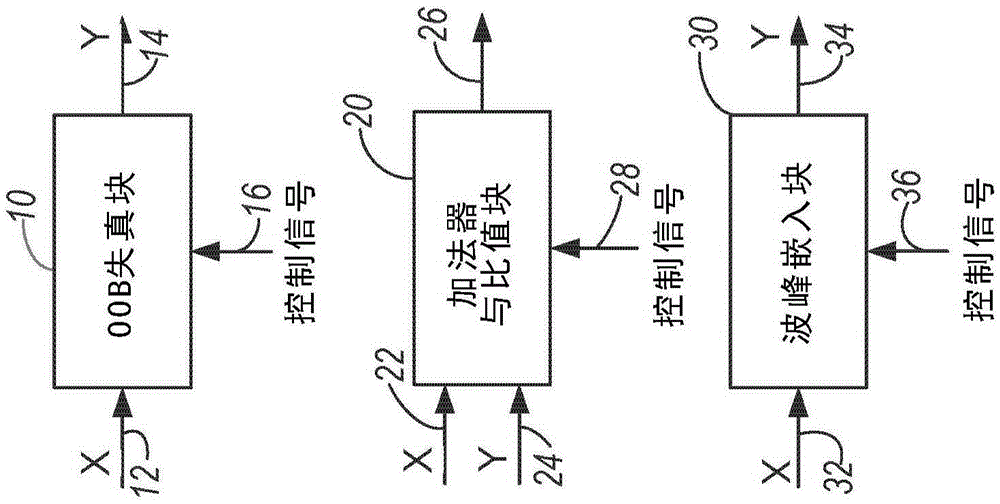
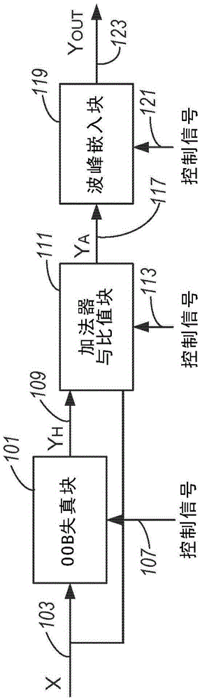
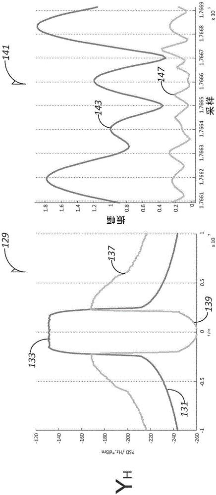
[0017] The current consumption of modern transmitter systems is highly dependent on the power amplifier. In some applications, within 3GPP specifications, the bias point of the power amplifier is selected to achieve a target average output power that maintains the linearity of the amplified signal. For non-constant envelope modulations, such as Wideband Code Division Multiple Access (WCDMA) or Orthogonal Frequency Division Multiplexing (OFDM), the high PAPR of the signal requires the bias point to be far from the optimum efficiency achievable by the power amplifier. Thus, having a signal with a low PAPR (which is usually achieved by a high CFR) and substantially the same data rate as would be available without that CFR translates directly into an efficiency advantage.

[0018] Worldwide Interoperability for Microwave Access (WiMAX) currently defined by the Institute of Electrical and Electronics Engineers (IEEE) 802.16-series of specifications due to the generally excellent pe...


PUM


Abstract

The invention provides a communication device with power amplifier crest factor reduction. Various embodiments include a power amplifier with crest factor reduction embodied by first circuitry for producing a correlated out-of-band noise signal for controlling the adjacent channel leakage ratio (ACLR) of a communication device; and second circuitry for providing an output signal for controlling the error vector magnitude (EVM) of a digital radio. The ACLR and the EVM are concurrently individually controllable. Additional apparatus is described.

Description

technical field [0001] Embodiments described herein relate to crest factor reduction (CFR) for power amplifiers. Some embodiments relate to radio frequency (RF) power amplifiers in communication devices. Some embodiments relate to user equipment (UE) in cellular networks, including Third Generation Partnership Partnership Long Term Evolution (3GPP LTE) networks. Background technique [0002] Many electronic devices, such as cellular handsets and computers, often include power amplifiers to increase the power level of signals for various applications. In these devices, the current consumption is highly dependent on the power amplifier. Therefore, the bias point of the power amplifier is usually chosen to obtain the target average output power within the desired linearity specification, while keeping the peak-to-average power ratio (PAPR) or crest factor low. Therefore, it is desirable to have a high CFR in the design of the power amplifier, which will cause the bias point ...

Claims


Application Information

Patent Timeline
IPC IPC(8): H03F1/02H03F3/189H03F3/20
CPCH03F1/02H03F3/189H04B1/0475H04B2001/0408H04L27/2614H03F3/24H04L27/26265H04L27/2623H04L27/3411H04L27/08
Inventor 阿莱西奥·法拉贝格丽伯恩哈德·索格简-艾瑞克·米勒
Owner INTEL IP CORP
Why Eureka
Try Eureka