
steam cleaner

A vacuum cleaner and steam technology, applied in vacuum cleaners, cleaning equipment, household appliances, etc., can solve problems such as poor flow performance, affecting the safe operation and service life of the steam cleaner, and poor heat dissipation of the motor, so as to promote the flow.

Active Publication Date: 2018-01-19
GUANGDONG MIDEA WHITE HOME APPLIANCE TECH INNOVATION CENT CO LTD +1
View PDF9 Cites 0 Cited by
  • Summary
  • Abstract
  • Description
  • Claims
  • Application Information

AI Technical Summary

Problems solved by technology

Among them, the heat dissipation of the fan affects the safe operation and service life of the steam cleaner. The air flow performance of the air duct in the related art is poor, which leads to poor heat dissipation of the motor and affects the safety performance of the steam cleaner.

Method used


Image

  • steam cleaner
  • steam cleaner
  • steam cleaner

Examples


Embodiment Construction

[0031] Embodiments of the present invention are described in detail below, examples of which are shown in the drawings, wherein the same or similar reference numerals designate the same or similar elements or elements having the same or similar functions throughout. The embodiments described below by referring to the figures are exemplary only for explaining the present invention and should not be construed as limiting the present invention.

[0032] In describing the present invention, it should be understood that the terms "center", "longitudinal", "transverse", "length", "width", "thickness", "upper", "lower", "front", " Back", "Left", "Right", "Vertical", "Horizontal", "Top", "Bottom", "Inner", "Outer", "Clockwise", "Counterclockwise", "Axial", The orientation or positional relationship indicated by "radial", "circumferential", etc. is based on the orientation or positional relationship shown in the drawings, and is only for the convenience of describing the present invent...


PUM


Abstract

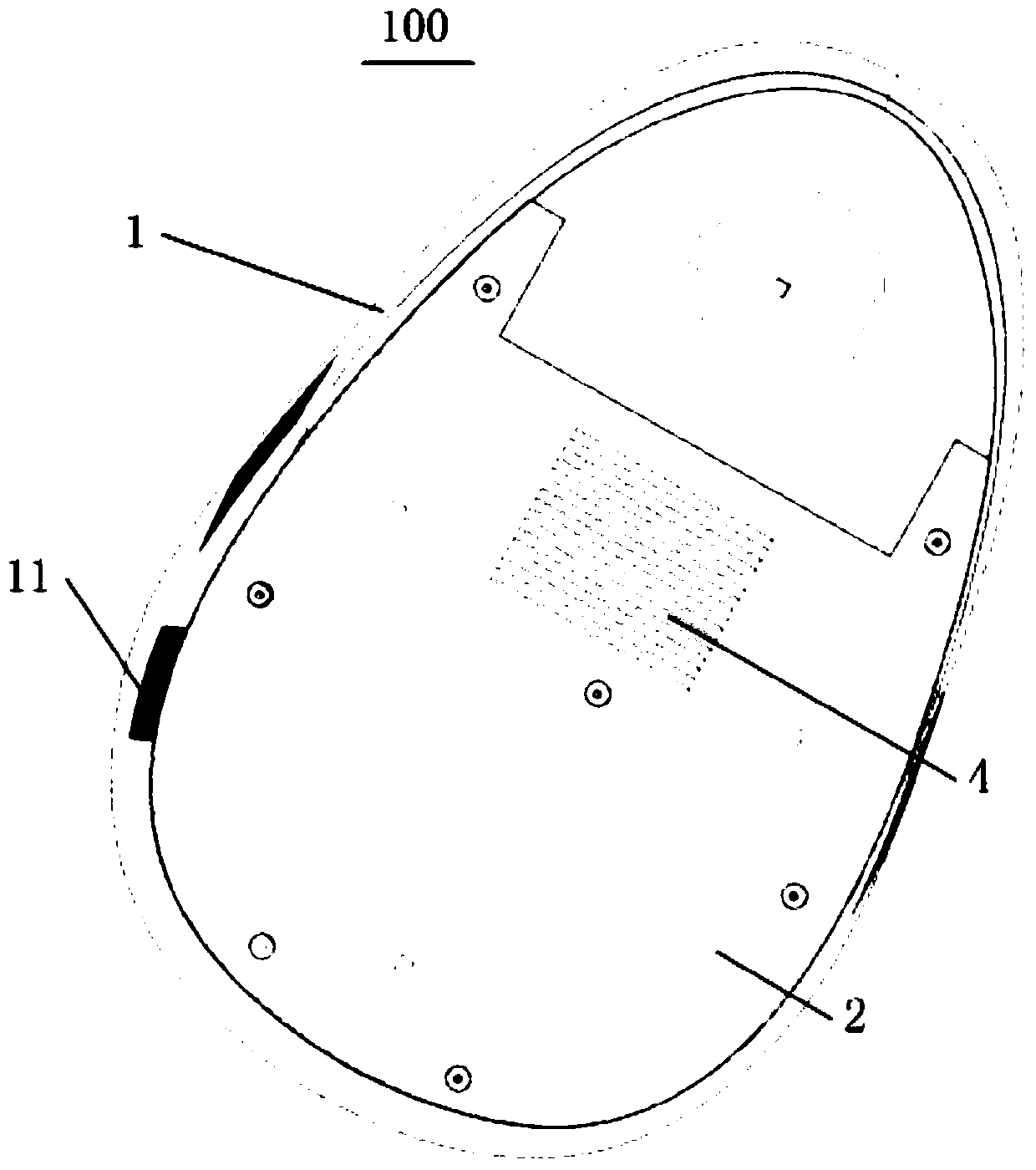
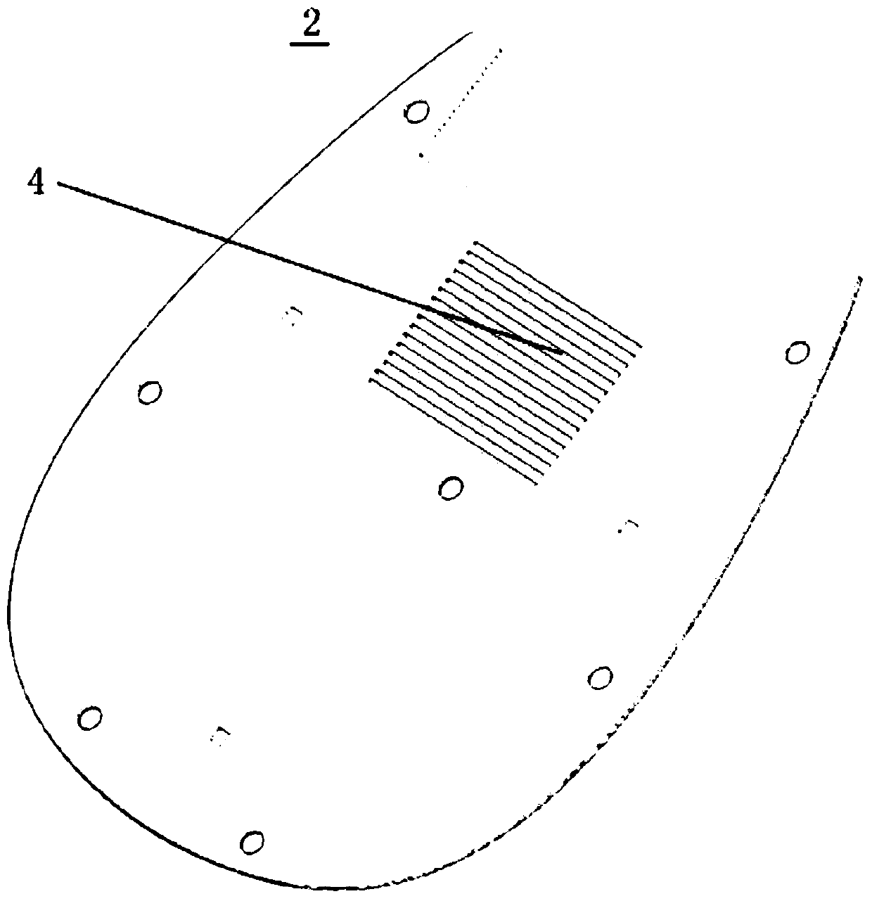
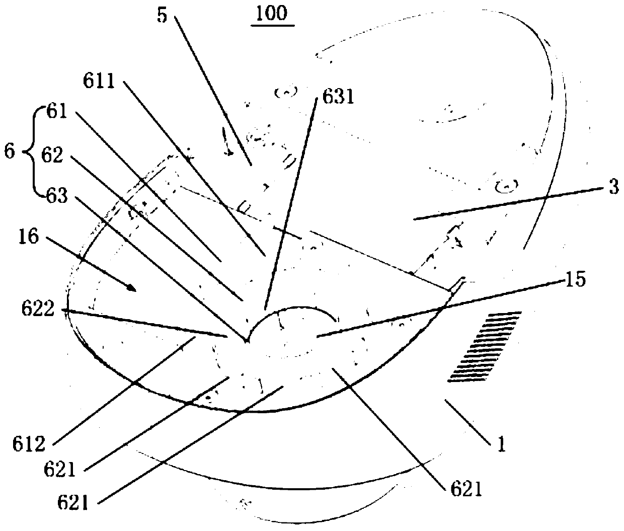
The invention discloses a steam dust collector, which comprises a base, a shell and a fan, wherein an air inlet is formed in the base; the shell is arranged on the base and air vents are formed in the sidewalls of the shell; an eddy current air duct is defined between the bottom wall of the shell and the base; the air inlet communicates with fluid in the eddy current air duct; the fan is arranged in the shell and comprises a motor and a heat radiating wind wheel which is connected to the lower end of a motor shaft of the motor, wherein the eddy current air duct is such configured that air entering from the air inlet is guided to the heat radiating wind wheel so as to radiate heat of the motor. According to the steam dust collector disclosed by the invention, by defining the eddy current air duct, which has functions of collecting flow and offering circumferential circulation before the air flows to the fan, between the shell and the base, the air can circulate in the eddy current air duct in a mode of gradually contracting. Therefore, the steam dust collector is conducive to air circulation towards the heat radiating wind wheel, so that the heat-radiating air is more aligned with flow regularity, and air circulation is promoted.

Description

technical field [0001] The invention relates to the technical field of vacuum cleaners, in particular to a steam vacuum cleaner. Background technique [0002] The steam vacuum cleaner in the prior art is powered by a high-speed centrifugal fan, sucks the garbage into the filter device of the steam cleaner, and through the separation of the downstream air and the garbage separation device, the garbage remains in the filter device, and the clean air is discharged outside the body. Among them, the heat dissipation of the fan affects the safe operation and service life of the steam cleaner. The air flow performance of the air duct in the related art is poor, which leads to poor heat dissipation of the motor and affects the safety performance of the steam cleaner. Contents of the invention [0003] The present invention aims to solve at least one of the technical problems existing in the prior art. Therefore, the present invention proposes a steam cleaner, the fan of the steam...

Claims


Application Information

Patent Timeline
Patent Type & Authority Patents(China)
IPC IPC(8): A47L9/00A47L7/04
CPCA47L7/04A47L9/00
Inventor 明乐乐张辉张冀喆徐前邓雁青
Owner GUANGDONG MIDEA WHITE HOME APPLIANCE TECH INNOVATION CENT CO LTD
Learn More