Portable tapered roller bearing race installation tool for automatic transmission remanufacturing

A technology for tapered roller bearings and automatic transmissions, which is applied in the manufacture of tools, hand-held tools, etc., can solve the problems of inconvenient installation of tapered roller bearing races, and achieve the effect of reducing remanufacturing costs

Active Publication Date: 2018-03-23
全椒康盛机电有限公司
View PDF9 Cites 0 Cited by
  • Summary
  • Abstract
  • Description
  • Claims
  • Application Information

AI Technical Summary

Problems solved by technology

[0003] The invention provides a portable tapered roller bearing seat ring installation tool for the remanufacturing of the automatic transmission that can conveniently install the tapered roller bearing seat ring, and solves the problem of installing the tapered roller bearing seat in the remanufacturing process of the automatic transmission. inconvenient problem

Method used


Image

  • Portable tapered roller bearing race installation tool for automatic transmission remanufacturing
  • Portable tapered roller bearing race installation tool for automatic transmission remanufacturing
  • Portable tapered roller bearing race installation tool for automatic transmission remanufacturing

Examples


Embodiment 1

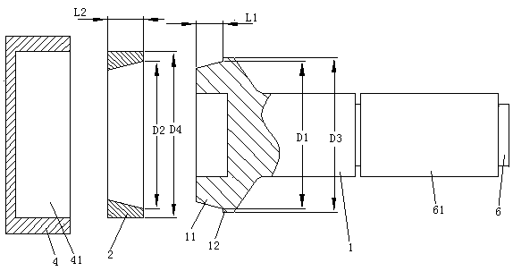
[0031] Embodiment one, see figure 1 , a portable tapered roller bearing race installation tool for automatic transmission remanufacturing, comprising a push rod 1. The right end of the push rod 1 is provided with a grip bar 6 . 6 sets of grip bars are provided with handle gloves 61 . The handle glove 61 is a rubber sheath. The left end of the push rod 1 is provided with a tapered shaft head 11 . The taper of the tapered shaft head 11 is equal to the taper of the tapered roller bearing race 2 . A pressing ring 12 extending along the circumference of the tapered shaft head is provided at the root of the tapered shaft head 11 . The diameter D1 of the root of the tapered shaft head is less than or equal to the inner diameter D2 of the large diameter end of the tapered roller bearing race. The length L1 of the tapered shaft head is less than or equal to the length L2 of the tapered roller bearing race. The outer diameter D3 of the pressing ring is smaller than or equal to the...

Embodiment 2

[0036] Embodiment two, the difference with embodiment one is;

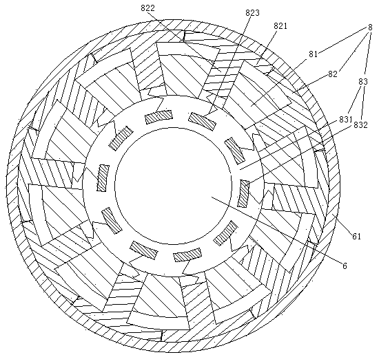
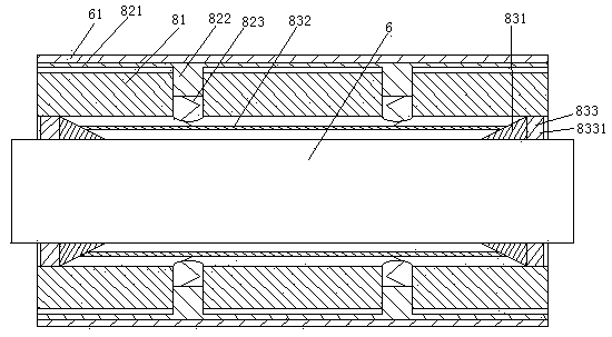
[0037] see Figure 4 , The push rod 1 is also provided with a seat ring dismounting booster mechanism 9. The booster mechanism 9 for seat ring disassembly and assembly includes a fan 91 , an air duct 92 and a wind direction conversion mechanism 93 . The fan 91 is provided with an air inlet 911 and an air outlet 912 . The fan 91 includes fan blades 913 and a motor 914 for driving the fan blades. The air duct 92 is an annular structure. The air duct 92 communicates with the air inlet 911 and the air outlet 912 . The air duct 92 is provided with an entrance and exit passage 921 , an entrance passage 922 and an exit passage 923 . The access channel 921 runs through the pressing ring 12 . The entrance and exit passage 921 is provided with an annular cylinder 924 extending circumferentially along the tapered shaft head 11 . The annular cylinder body 924 is sealed and slidably connected with an annular thimble dri...


PUM


Abstract

The invention relates to the technical field of automatic transmission reproducing. A portable tapered roller bearing race mounting tool for reproducing an automatic transmission is characterized by comprising a push rod, wherein one end of the push rod is provided with a tapered shaft head; the taper of the tapered shaft head is equal to that of a tapered roller bearing race; the root part of the tapered shaft head is provided with a pressing ring extending in a circumferential direction of the tapered shaft head; the diameter of the root part of the tapered shaft head is not larger than the internal diameter of the large diameter end of the tapered roller bearing race; and the other end of the push rod is provided with a holding rod. The invention provides the portable tapered roller bearing race mounting tool for reproducing the automatic transmission, which can conveniently mount the tapered roller bearing race; and a problem that the tapered roller bearing race is inconvenient to mount in the automatic transmission reproducing process is solved.

Description

technical field [0001] The invention relates to the technical field of remanufacturing of automatic transmissions, in particular to a portable tapered roller bearing race installation tool for remanufacturing of automatic transmissions. Background technique [0002] The tapered roller bearing installed in the transmission is supported by the tapered roller bearing race in the shaft hole where the tapered roller bearing is installed in the transmission. During the reconstruction process of automatic transmission, it is necessary to install the tapered roller bearing race into the shaft hole where the tapered roller bearing is installed. The existing method of installing the tapered roller bearing race is to align the race with the shaft hole of the part where the tapered roller bearing race is installed by hand, and then press the tapered roller bearing seat by hand or tap it with a hammer. In terms of ring installation, this method is not only very inconvenient to install, ...

Claims


Application Information

Patent Timeline
Patent Type & Authority Patents(China)
IPC IPC(8): B25B27/06
CPCB25B27/06
Inventor 危金兰
Owner 全椒康盛机电有限公司
Why Eureka
Try Eureka