Turn light system of electric wheelbarrow

A turn signal and unicycle technology, applied in the field of self-balancing electric unicycle structure, can solve problems such as failure to reach the unicycle, potential safety hazards, and inability of the unicycle to indicate the turning direction

Inactive Publication Date: 2016-06-29
李陈
View PDF8 Cites 2 Cited by
  • Summary
  • Abstract
  • Description
  • Claims
  • Application Information

AI Technical Summary

Problems solved by technology

The existing electric unicycle does not have a turn signal, so the unicycle cannot indicate the turning direction when it needs to turn when driving on the road, and there are certain safety hazards
The manufacturers of the unic...

Method used


Image

  • Turn light system of electric wheelbarrow
  • Turn light system of electric wheelbarrow
  • Turn light system of electric wheelbarrow

Examples


Embodiment 1

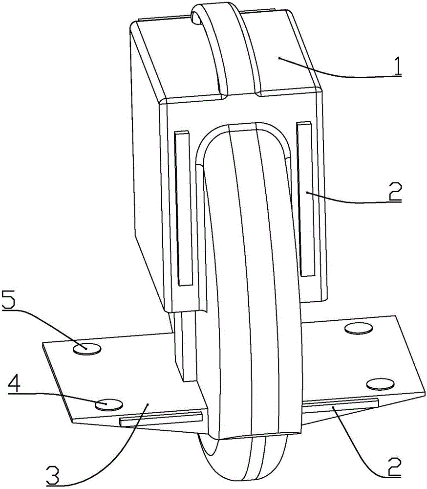
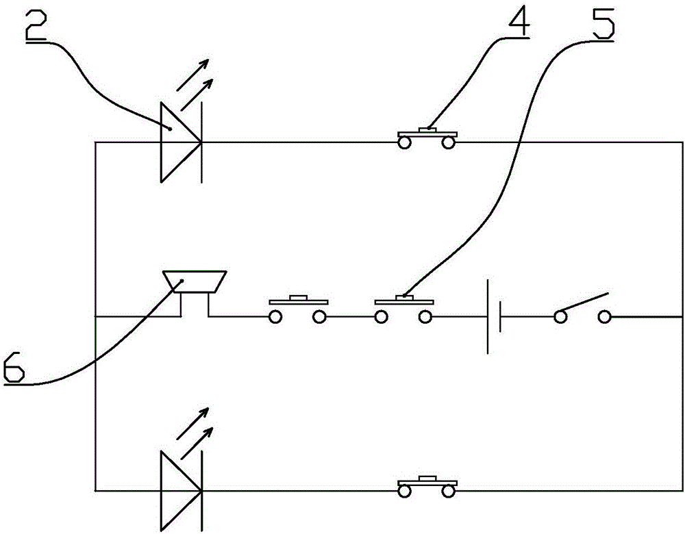
[0030] according to figure 1 with figure 2 As shown, a kind of electric unicycle turning signal system described in the present embodiment includes turning lights 2 installed on the left and right sides of the front and / or rear of the unicycle body 1, and on the two pedals 3 on both sides of the unicycle. A normally closed contact switch 4 for controlling the turn signal on and off and a normally open contact switch 5 for judging whether both feet of the rider are standing on the pedal are installed; the normally open contact switch is installed on the front half of the pedal above, the normally closed contact switch is installed above the rear half of the pedal; the turn signal on the left is connected in series with the normally closed contact switch on the right, two normally open contact switches on both sides and the power supply, The turn signal on the right is connected in series with the normally closed contact switch on the left, two normally open contact switches ...

Embodiment 2

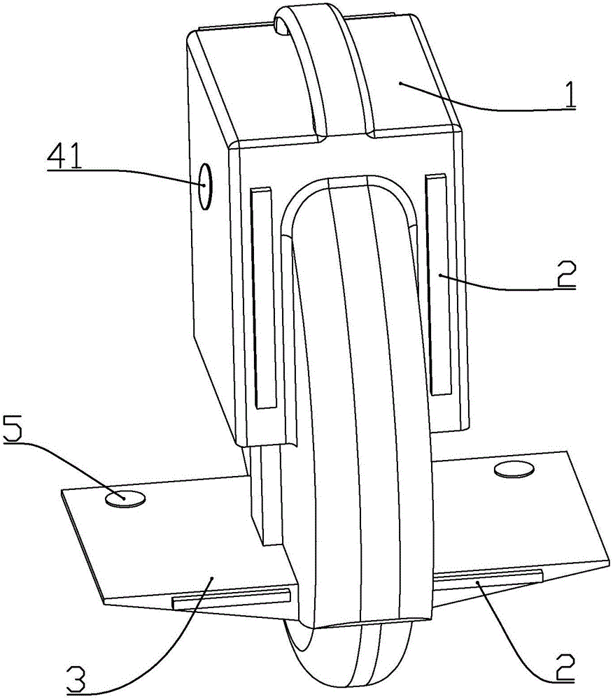
[0033] according to image 3 with Figure 4 As shown, a kind of electric unicycle turn signal system described in this embodiment includes turn signal lights 2 installed on the left and right sides of the front and / or rear of the unicycle body 1, and are installed on the two pedals on both sides of the unicycle. There is normally open contact switch 5 in order to judge whether both feet of the rider stand on the pedal, and the normally open contact switch is installed on the top of the front half of pedal 3; The push switch 41 of the turn signal on and off; The two normally open contact switches on the side and the power supply are connected in series. A buzzer 6 or a voice playback module for prompting the on-state of the turn signal is also connected in series on the line of the two normally open contact switches.

[0034] When in use, when the user steps on the pedal of the unicycle, the two normally open contact switches are closed, and the two normally open contact swi...

Embodiment 3

[0036] according to Figure 5 to Figure 8 As shown, a kind of electric unicycle turn signal system described in this embodiment includes turn signal lights 2 installed on the left and right sides of the front and / or rear of the unicycle body 1, and are installed on the two pedals on both sides of the unicycle. There is a confirmation button switch 50 for judging whether both feet of the rider stand on the pedal 3, and a control button switch 40 for controlling the on-off of the turn signal; the confirmation button switch is installed on the top of the front half of the pedal; The control button switch is installed above the rear half of the pedal; the two confirmation button switches are connected in series with the input terminals of the controller, and the two control button switches are respectively connected to the two input terminals of the controller; The turning lights are respectively connected to the two output terminals of the controller, the turning lights on the le...


PUM


Abstract

The invention discloses a turn light system of an electric wheelbarrow. The turn light system comprises a turn light mounted at the front part of the wheelbarrow body and/or on the left and right sides of the back part; two pedals on the two sides of the wheelbarrow are both provided with a confirm button switch for judging whether both feet of a rider step on the pedals and a control button switch for controlling the on/off of the turn light; the confirm button switch is mounted above the front half of the pedal; the control button switch is mounted above the back half of the pedal; and the turn light on the left side is controlled by the control button switch on the right side while the turn light on the right side is controlled by the control button switch on the left side. Through adaptive design according to the stress state of the feet when the user rides the wheelbarrow, the turn light system is convenient to control and has high practicability.

Description

[0001] This patent is: [0002] Name: Electric Solo Trump Turn Light System [0003] The application number is: 2014103635158 [0004] The application date is: 2014.07.28 [0005] Application for patent applications. Technical field [0006] The present invention belongs to the field of self -balanced electric single -wheel wheels, which involves the steering light system of electric unicycles. Background technique [0007] Electric single -wheel car is a kind of power -driven and self -balanced transportation.Today, with the rapid development of society, traffic congestion has also become the final phenomenon. Electric single -wheeled vehicles instead of bicycles and electric vehicles are the development of fashion.The rise of electric unique trucks will soon trigger a new traffic revolution.The existing electric unless wheel car does not have a steering light, so that the single wheel vehicle needs to indicate the direction of the turning direction when driving on the road, and ...

Claims


Application Information

Patent Timeline
IPC IPC(8): B62J6/00B62J6/16B62J3/00B62K11/00
CPCB62J3/00B62J6/05B62J6/057B62J6/16B62K11/00B62K2204/00
Inventor 李陈
Owner 李陈
Why Eureka
Try Eureka