Variable-diameter mixing pile machine, its pile-forming construction method, and drill pipe

A technology for mixing pile drivers and drill pipes, applied in the field of mixing piles, which can solve the problems of inability to achieve stepless diameter reduction, poor construction quality, and unopened movable blades, so as to improve mixing efficiency, reduce the time for replacing mixing blades, Solve the effect of bubbling

Active Publication Date: 2018-07-03
江苏路鼎智能科技有限公司
View PDF7 Cites 0 Cited by
  • Summary
  • Abstract
  • Description
  • Claims
  • Application Information

AI Technical Summary

Problems solved by technology

However, the variable-diameter mixing pile machine still has the following problems: (1) After changing the direction of rotation, the movable blades are not opened or not fully opened, and the construction of variable pile diameters is not completed according to the design requirements, or the construction quality is poor; (2) Only two kinds of pile diameters can be realized, and stepless variable diameters cannot be realized

Method used


Image

  • Variable-diameter mixing pile machine, its pile-forming construction method, and drill pipe
  • Variable-diameter mixing pile machine, its pile-forming construction method, and drill pipe
  • Variable-diameter mixing pile machine, its pile-forming construction method, and drill pipe

Examples


Embodiment 1

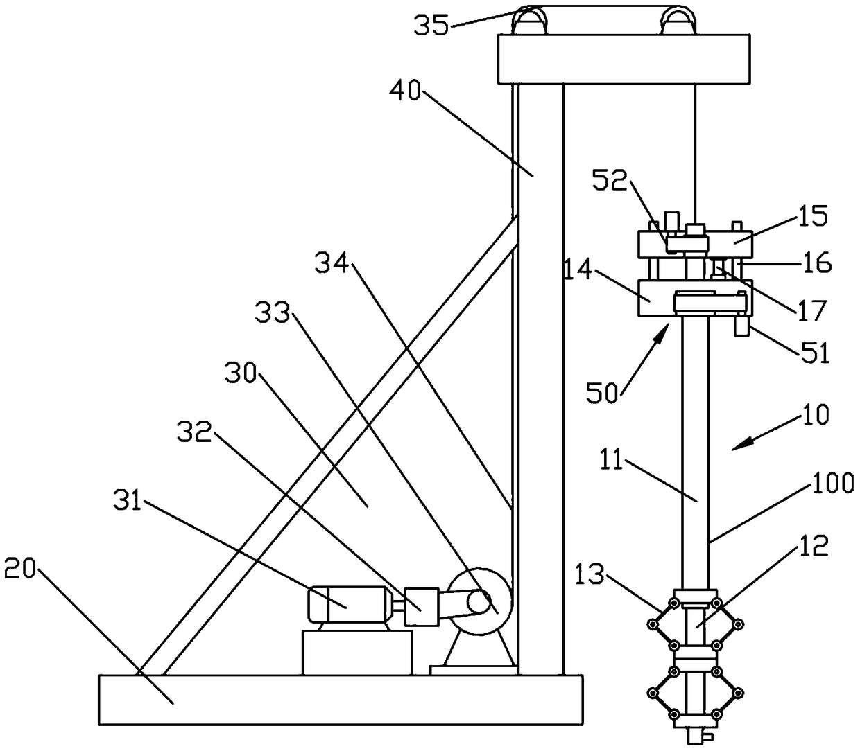
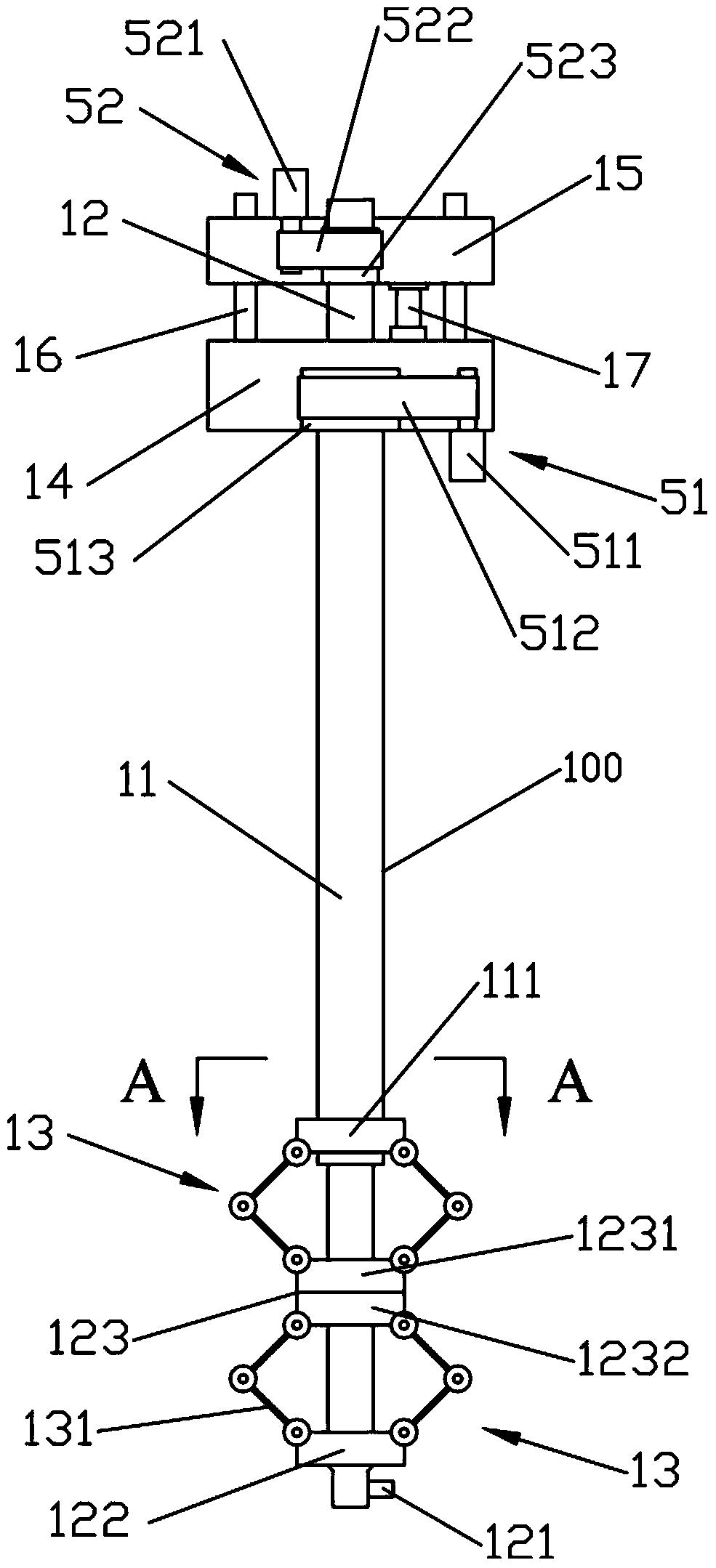
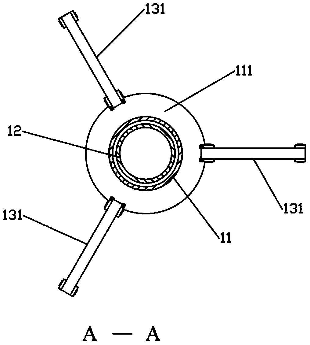
[0048] Such as Figures 1 to 4 As shown, the variable-diameter stirring pile driver of the present invention includes: a machine base 20 , a tower 40 , a stirring head 10 and a lifting mechanism 30 . The tower 40 is fixed on the base 20 . The stirring head 10 is hoisted on the tower 40 through the lifting mechanism 30, and the lifting mechanism 30 drives the stirring head 10 to move up and down. Lifting mechanism 30 has multiple structures such as rope rower formula, electric hoist formula or lifting slide rail formula, all are prior art. refer to figure 1 As shown, in the present embodiment, the rope rower type is adopted, and the lifting mechanism 30 includes a lifting motor 31, a lifting reducer 32, a steel wire rope 34, a lifting roller 35 and a lifting reel 33, and the lifting motor 31 is installed on the base 20. Speed ​​reducer 32 is connected with lifting reel 33, drives lifting reel 33 to rotate, and lifting roller 35 is installed on the tower frame 40. One end of...

Embodiment 2

[0055] This embodiment is basically the same as Embodiment 1, the difference is: refer to Figure 8As shown, two groups of stirring blade groups 13 are hingedly installed between the outer tube spokes 111 and the upper spokes 1231, and the adjacent two groups of stirring blades 13 are hinged through an upper sliding spoke 124, and the upper sliding spokes 124 is slidably mounted on the outer wall of the inner tube 12 and is located between the outer tube spoke 111 and the upper spoke 1231 . Two sets of stirring blade groups 13 are hingedly installed between the inner tube spoke 122 and the lower spoke 1232, and the adjacent two sets of stirring blades 13 are hinged through a lower sliding spoke 125, and the lower sliding spoke 125 can slide It is installed on the outer wall of the inner tube 12, between the inner tube spoke 122 and the lower spoke 1232. In order to ensure better grout pressure during the process of stirring into piles and avoid the generation of grout, the nu...

Embodiment 3

[0058] This embodiment is basically the same as Embodiment 1 and 2, the difference is that: with reference to Figure 9 As shown, the steel wire rope 34 is connected with the outer pipe head seat 14, the outer pipe head seat 14 is provided with a guide rod 16, the inner pipe head seat 15 is provided with a guide hole matched with the guide rod 16, and the inner pipe head seat 15 and the guide rod 16 Slidably socketed, and the upper end of the guide rod 16 passes through the inner pipe head seat 15; The rod 16 moves.


PUM


Abstract

The invention relates to the technical field of mixing piles, and discloses a reducing mixing pile machine. The reducing mixing pile machine comprises a machine base, a tower, a mixing head and a lifting mechanism. The tower is fixed to the machine base. The mixing head is hoisted on the tower through the lifting mechanism. The mixing head comprises a drill pipe, a rotation driving mechanism and a telescopic mechanism. The drill pipe comprises an outer pipe and an inner pipe, and the inner pipe is sleeved with the outer pipe. A grout spraying nozzle is arranged on the front portion of the inner pipe. The rotation driving mechanism is connected with the outer pipe and the inner pipe. The telescopic mechanism drives the inner pipe and the outer pipe to relatively move. The outer pipe is provided with an outer pipe radial ring, and an inner pipe radial ring is arranged on the front portion of the inner pipe. A slidable transition sleeve is further arranged on the front portion of the inner pipe and provided with an upper radial ring and a lower radial ring, and the upper radial ring and the lower radial ring can rotate relatively. At least one mixing blade set is hinged between the outer pipe radial ring and the upper radial ring, and at least one mixing blade set is hinged between the inner pipe radial ring and the lower radial ring. Each mixing blade set comprises at least one mixing blade. Each mixing blade comprises a first blade body and a second blade body hinged to the first blade body. The invention further provides a pile forming construction method and the drill pipe.

Description

technical field [0001] The invention relates to the technical field of stirring piles, in particular to a variable-diameter stirring pile machine, a pile-forming construction method thereof, and a drill pipe. Background technique [0002] Soft soil foundation treatment in building foundation engineering is the key link to ensure the quality of the project, and it occupies a large proportion of the total project price. A large number of engineering practices have shown that the cement-soil mixing pile method has the advantages of simple construction, rapid construction, and small vibration, which can effectively improve the stability of soft soil foundations and reduce and control settlement. Cement-soil mixing piles have been developed into a commonly used soft ground treatment method, which is mainly suitable for the reinforcement of saturated soft clay ground. Specifically, the cement (or lime) and other curing agents are pumped into the soft soil by using the pile mixer,...

Claims


Application Information

Patent Timeline
Patent Type & Authority Patents(China)
IPC IPC(8): E02D5/46E21B17/18
Inventor 宫能和
Owner 江苏路鼎智能科技有限公司
Why Eureka
Try Eureka