Hydraulic control system and control method for excavators

A hydraulic control system and excavator technology, applied in mechanically driven excavators/dredgers, earth movers/shovels, construction, etc. The effect of working efficiency and improving the efficiency of leveling

Active Publication Date: 2016-06-29
LIUZHOU LIUGONG EXCAVATORS +2
View PDF4 Cites 27 Cited by
  • Summary
  • Abstract
  • Description
  • Claims
  • Application Information

AI Technical Summary

Benefits of technology

This patented technology helps operators better manage their machines' performance through monitoring various factors like engine speed, load weight, etc., while reducing the effort required to perform tasks such as leveling. By measuring these variables overall, the technical effect of this innovative system is improved efficient maintenance of equipment used in industrial environments.

Problems solved by technology

This technical problem addressed by this patented technology relates to improving an excavator's ability to operate at varying levels or types during operation based upon its current settings for optimal performance without requiring manual adjustments made by users who may have no understanding about their specific circumstances.

Method used


Image

  • Hydraulic control system and control method for excavators

Examples


Embodiment Construction

[0022] The specific implementation will be described below in conjunction with the accompanying drawings.

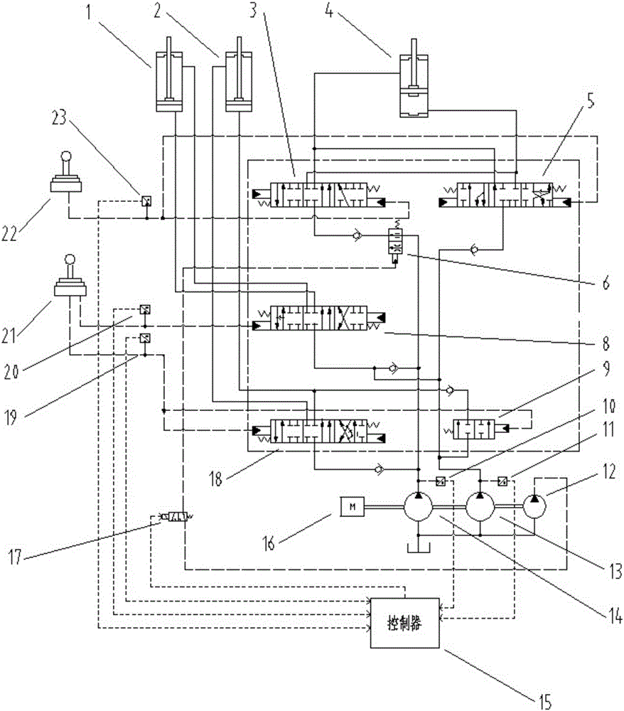
[0023] Such as figure 1 As shown, the excavator hydraulic control system in this embodiment includes bucket cylinder 1, boom cylinder 2, stick confluence valve 3, stick cylinder 4, stick control valve 5, flow regulating valve 6, bucket cylinder control Valve 8, boom confluence valve 9, left pump pressure sensor 10, right pump pressure sensor 11, pilot pump 12, right pump 13, left pump 14, controller 15, engine 16, on-off switch solenoid valve 17, boom control Valve 18, boom lifting pilot pressure sensor 19, bucket recovery pilot pressure sensor 21, right pilot valve 21, left pilot valve 22, arm recovery pilot pressure sensor 23.

[0024] The engine 16 drives the pilot pump 12, the right pump 13, and the left pump 14; the stick cylinder control valve includes the stick confluence valve 3 and the stick control valve 5, and the pump port of the right pump 13 passes through...


PUM


Abstract

The invention relates to hydraulic control over excavators and provides a hydraulic control system for the excavators. The hydraulic control system aims to solve the problem that the existing hydraulic control modes of the excavators are manually controlled for being switched. The hydraulic control system for the excavators comprises a controller, pressure sensors and a flow control device, wherein the electronic control end of the flow control device is connected to the controller; a main pump pressure preset value and a pilot pressure preset value are preset in the controller. According to the hydraulic control system and a control method for the excavators, whether a machine is under the flat working condition or the excavation working condition is judged by detecting relevant parameters of hydraulic oil, the working modes under the two working conditions can be automatically switched, and the work intensity of operators can be lowered on the premise of improving the work efficiency of the machine.

Description


Claims


Application Information

Patent Timeline
Owner LIUZHOU LIUGONG EXCAVATORS
Why Eureka
Try Eureka