
A construction method of sand blasting and backfilling grouting for tunnels passing through goafs in coal mines

A construction method and goaf technology, which is applied to filling materials, mining equipment, earthwork drilling and mining, etc., can solve problems such as water inrush, mud inrush and landslides, abnormal tunnel excavation, and threats to the safety of construction workers. problems, achieve high structural safety requirements, reduce construction risks, and save material consumption

Active Publication Date: 2020-11-03
赵立财
View PDF6 Cites 0 Cited by
  • Summary
  • Abstract
  • Description
  • Claims
  • Application Information

AI Technical Summary

Problems solved by technology

[0002] At present, the overlying strata in the goaf of the coal mine are unstable, and the lithology is mainly mudstone and sandy mudstone. The surrounding rocks near the gob are mostly coal seams or coal gangue formations. The water in the cavern is serious, and the surrounding rock is weak and broken, and it is easy to weather and peel off. , no self-stabilization ability, prone to water inrush, mud inrush and landslide after disturbance
Conventional methods such as “full-fill pressure grouting and advanced curtain grouting” cannot be used to backfill gobs when constructing tunnels under such geological conditions. These traditional construction methods inject cement grout directly into the goaf, which causes construction problems. The load is all borne by the overburden strata. Generally, it takes a long time for backfilling and grouting in the goaf before the tunnel excavation can be carried out. It takes a long time for the overburden strata to bear the load of the surrounding rock. For the coal mine goaf formation, it takes a long time during this period. It is very prone to collapse, water and mud inrush accidents, making the tunnel excavation impossible, threatening the safety of construction workers, delaying the overall construction period, and increasing project investment costs

Method used


Image

  • A construction method of sand blasting and backfilling grouting for tunnels passing through goafs in coal mines
  • A construction method of sand blasting and backfilling grouting for tunnels passing through goafs in coal mines

Examples


Embodiment Construction

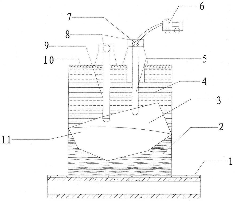
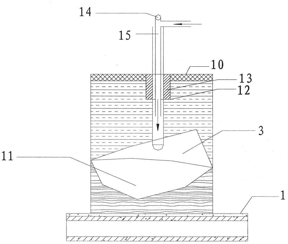
[0030] Embodiments of the present invention will be further described in detail below in conjunction with the accompanying drawings and examples. The following examples are used to illustrate the present invention, but should not be used to limit the scope of the present invention.

[0031] In the description of the present invention, it should be noted that unless otherwise specified, the meaning of "plurality" is two or more; the terms "upper", "lower", "left", "right", "inner ", "outside", "front end", "rear end", "head", "tail", etc. indicate the orientation or positional relationship based on the orientation or positional relationship shown in the drawings, and are only for the convenience of describing the present invention and Simplified descriptions, rather than indicating or implying that the device or element referred to must have a particular orientation, be constructed and operate in a particular orientation, and thus should not be construed as limiting the inventi...


PUM


Abstract

The invention relates to the technical field of tunnel construction, in particular to a blowing sand backfill and grouting construction method of a tunnel crossing coal mine goaf.By means of the method, the coal mine goaf can be accurately verified aiming at blowing sand backfill and grouting construction of highway and railway tunnels crossing coal mine goaf with unstable overlaying rock to achieve informatization and mechanization of backfill construction of the tunnel crossing the coal mine goaf, artificial missing detection or misjudgment is reduced, a construction risk is reduced to the minimum extent, the blowing sand backfill and grouting construction method of the tunnel crossing the coal mine goaf is specially suitable for backfill and grouting treatment construction of high-speed railway tunnels crossing the coal mine goaf, and the construction has the requirements of being tight in construction period, high in structural safety requirement, great in construction difficulty and the like.

Description

technical field [0001] The invention relates to the technical field of tunnel construction, in particular to a sand blowing backfill grouting construction method for a tunnel passing through a coal mine goaf. Background technique [0002] At present, the overlying strata in the goaf of the coal mine are unstable, and the lithology is mainly mudstone and sandy mudstone. The surrounding rocks near the gob are mostly coal seams or coal gangue formations. The water in the cavern is serious, and the surrounding rock is weak and broken, and it is easy to weather and peel off. , no self-stabilization ability, water inrush, mud outburst and landslides are prone to occur after disturbance. Conventional methods such as “full-fill pressure grouting and advanced curtain grouting” cannot be used to backfill gobs when constructing tunnels under such geological conditions. These traditional construction methods inject cement grout directly into the goaf, which causes construction problems....

Claims


Application Information

Patent Timeline
Patent Type & Authority Patents(China)
IPC IPC(8): E21F15/00
CPCE21F15/00
Inventor 赵立财
Owner 赵立财
Features
  • Generate Ideas
  • Intellectual Property
  • Life Sciences
  • Materials
  • Tech Scout
  • Unparalleled Data Quality
  • Higher Quality Content
  • 60% Fewer Hallucinations
Learn More