A collaborative control method for electric heating groups

A collaborative control, electric heating technology, applied in heating methods, space heating and ventilation details, lighting and heating equipment, etc., can solve problems such as load curve fluctuations

Active Publication Date: 2019-05-07
SHANGHAI SHANGTA SOFTWARE DEV CO LTD
View PDF10 Cites 0 Cited by
  • Summary
  • Abstract
  • Description
  • Claims
  • Application Information

AI Technical Summary

Problems solved by technology

Such a rough control method will lead to fluctuations in the load curve, which will impose high requirements on the capacity of transformers, circuit breakers and many other equipment

Method used


Image

  • A collaborative control method for electric heating groups
  • A collaborative control method for electric heating groups
  • A collaborative control method for electric heating groups

Examples


Embodiment 1

[0020] The collaborative control method for the stable operation state of the electric heating group is described as follows:

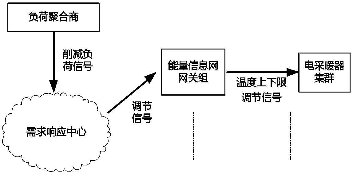
[0021] (1) In a residential area or an office building, arrange a sufficient number of electric heaters, recorded as N units. All electric heaters are connected to the cloud-controlled intelligent power platform to participate in regulation through energy efficiency terminals, energy information gateways and other equipment. At this time, the electric heaters of this cluster can be taken as a whole to adopt a corresponding collaborative control method;

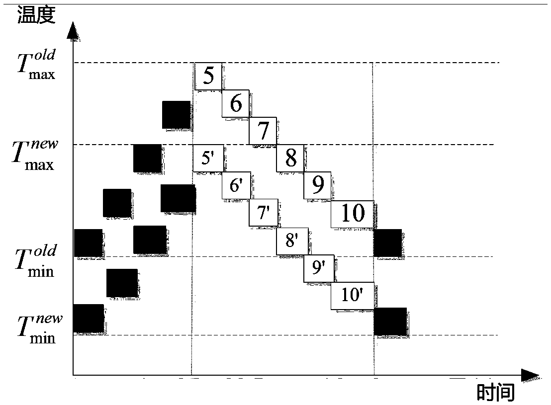
[0022] (2) Stable operating state, which means that the temperature of the heating environment is stable at the upper and lower limits of the set temperature [Tmin, Tmax], and the set temperature threshold is not adjusted. Combined with the mathematical model of heating and heat preservation of this kind of electric heater, the N electric heaters are evenly divided into M groups, and according to the ...

Embodiment 2

[0028] Assemble 50 electric heaters of the same model in one heating area, such as a carbon crystal heater with a rated power of 1500W. The 50 electric heaters are equally divided into 10 heating groups, and the 10 heating groups are numbered once, and each heating group governs 5 heaters, which is convenient for control.

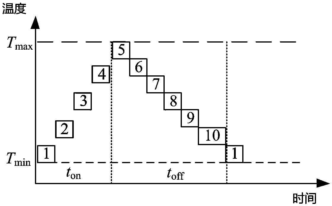
[0029] According to the coordinated control method of electric heating groups, in a steady state, each heating group starts up sequentially. The unit time is controlled according to the thermodynamic model of the electric heater. For example, the carbon crystal heater can take 10 minutes as the unit interval time. The states in the steady state are shown in the table below, where states 1, 2, 3 and 4 are on, and states 5-10 are off:

[0030]

[0031] 100 1-1 2-2 3-3 4-4 5-5 6-6 7-7 8-8 9-9

[0032] 10-10 4 groups

[0033] It can be seen from the above table that after adopting the coordinated control method of electric heating groups, the number of el...


PUM


Abstract

The invention discloses an electric heating cluster cooperative control method. The method comprises an electric heating cluster stable operating state cooperative control method and an electric heating cluster temperature adjusting state control method. The electric heating cluster stable operating state cooperative control method includes the steps that sufficient electric heaters are arranged in a residence community or an office building, the number of the electric heaters is N, all the electric heaters are connected with an intelligent electricity use platform controlled by a cloud through energy efficiency terminals and energy information gateways to participate in adjustment, at this moment, the electric heaters in the cluster are used as a whole, and the corresponding cooperative control method is adopted. The electric heating cluster temperature adjusting state control method includes the steps that information of an electricity generation side and information of an electricity use side are integrated through a demand response center, and it is ensured that load reducing signals are issued; and when the loads need to be reduced, the demand response center issues the load reducing signals to an intelligent electric heating platform cloud, the load reducing signals are then sent to the corresponding gateways through the intelligent electric heating platform cloud, and the load reducing signals are converted into adjusting signals of the electric heaters through the gateways.

Description

technical field [0001] The invention relates to the field of automatic control and demand side management, in particular to a method for collaborative control of electric heating groups. Background technique [0002] With the development of social economy, residents in southern regions also expect heating in winter. Considering the specific conditions in the southern region, decentralized electric heating is more suitable for popularization and application. Electric heaters are devices that convert electrical energy into heat energy, including electric heaters, carbon crystal heaters, etc. On the one hand, electric heaters often have large power, and corresponding energy-saving control measures should be taken to achieve higher energy efficiency; Load can play an active role in demand response. [0003] The existing local control method is too simple, usually according to the local temperature signal, multiple heating devices are turned on or off in a centralized way. Su...

Claims


Application Information

Patent Timeline
Patent Type & Authority Patents(China)
IPC IPC(8): F24D19/10
CPCF24D19/1096
Inventor 何光宇王彬何果红何勃兴
Owner SHANGHAI SHANGTA SOFTWARE DEV CO LTD
Why Eureka
Try Eureka