Supercharge Your Innovation With Domain-Expert AI Agents!

Leaf crown working face abrasion detecting tool

A technology for detecting tools and working surfaces, which is applied in the direction of measuring devices, instruments, etc., can solve problems such as the inability to meet the needs of rapid detection of repaired parts in mass production, and achieve the effects of reliable structure, convenient storage, and simple use

Inactive Publication Date: 2016-06-29
AECC SHENYANG ENGINE RES INST
View PDF5 Cites 0 Cited by
  • Summary
  • Abstract
  • Description
  • Claims
  • Application Information

AI Technical Summary

Problems solved by technology

[0003] For the measurement of the working face of the blade crown, three-coordinate measuring instruments or complex tooling are mainly used for detection at present, which cannot meet the rapid detection requirements of mass production and repaired parts. It is necessary to design a simple, fast and economical detection tool to meet the above Require

Method used


Image

  • Leaf crown working face abrasion detecting tool

Examples


Embodiment 1

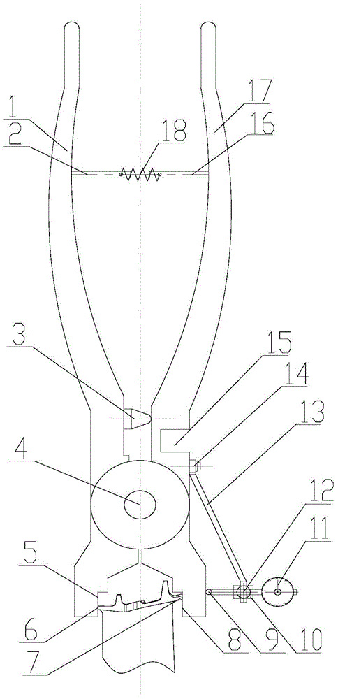
[0015] This embodiment provides a wear detection tool for the working face of the blade shroud, which is characterized in that: the wear detection tool for the working face of the blade shroud includes a pressing handle I1, a pull rod I2, a rotating shaft 4, a measuring chuck I5, and a front edge of the shroud 6. Trailing edge of leaf crown 7, measuring chuck II8, measuring gauge head 9, clamping frame 10, measuring gauge 11, knurled screw 12, bracket 13, pin shaft 14, stabilizing groove 15, pull rod II16, compression handle II17 , tension spring 18;

[0016] Among them: the compression handle I1 is integrated with the measuring chuck II8, the compression handle II17 is integrated with the measuring chuck I5, and the two are hinged through the rotating shaft 4; A pull rod II16 is installed on the inner side of the tail of the handle II17; a tension spring 18 is installed between the pull rod I2 and the pull rod II16;

[0017] There is a stabilizing groove 15 on the outside of...

Embodiment 2

[0021] This embodiment provides a wear detection tool for the working face of the blade shroud, which is characterized in that: the wear detection tool for the working face of the blade shroud includes a pressing handle I1, a pull rod I2, a rotating shaft 4, a measuring chuck I5, and a front edge of the shroud 6. Trailing edge of leaf crown 7, measuring chuck II8, measuring gauge head 9, clamping frame 10, measuring gauge 11, knurled screw 12, bracket 13, pin shaft 14, stabilizing groove 15, pull rod II16, compression handle II17 , tension spring 18;

[0022] Among them: the compression handle I1 is integrated with the measuring chuck II8, the compression handle II17 is integrated with the measuring chuck I5, and the two are hinged through the rotating shaft 4; A pull rod II16 is installed on the inner side of the tail of the handle II17; a tension spring 18 is installed between the pull rod I2 and the pull rod II16;

[0023] There is a stabilizing groove 15 on the outside of...


PUM


Abstract

A wear detection tool for a blade shroud face, characterized in that it includes a compression handle I, a pull rod I, a rotating shaft, a measuring chuck I, a blade shroud front edge, a blade shroud trailing edge, a measuring chuck II, a measuring gauge head, a clamping Frame, measuring table, knurled screw, bracket, pin shaft, stabilizing groove, pull rod II, compression handle II, tension spring; compression handle I and measuring chuck II are integrated structure, compression handle II and measuring chuck I is an integral structure, and the two are hinged by a rotating shaft; a pull rod I is installed on the inside of the tail of the compression handle I, and a pull rod II is installed on the inside of the tail of the compression handle II; a tension spring is installed between the pull rod I and the pull rod II; There is a stabilizing groove on the outside of the middle part of the tight handle II; a pin shaft is installed on the outside of the middle part of the tight handle II. The invention has the advantages of reliable structure, simple use, accurate, reliable and fast data measurement, disassembly and assembly, and can be widely used in the wear detection of the crowned blade working face.

Description

technical field [0001] The invention relates to the field of detection devices for the wear amount of the shroud working surface of the turbine rotor shrouded blade of a gas turbine or an aeroengine, and in particular relates to a wear detection tool for the working surface of the blade shroud. Background technique [0002] At present, the blade crowns of engine and gas turbine rotor blades are widely designed with sawtooth crown structure. When the blade is working, the tight fit of the working surface can suppress the rotor vibration and enhance the rigidity of the rotor. The sawtooth crown is generally composed of tenon, blade body and blade crown. The crown has a working surface and a non-working surface. When the blade is assembled, there is tightness on the working surface and a gap on the non-working surface. In order to ensure that the working surface with blade tightness has a reasonable tightness during engine assembly, it is necessary to measure the working surfac...

Claims


Application Information

Patent Timeline
Patent Type & Authority Applications(China)
IPC IPC(8): G01B21/00
Inventor 马增祥李鑫杨养花张超赵东明
Owner AECC SHENYANG ENGINE RES INST
Features
  • R&D
  • Intellectual Property
  • Life Sciences
  • Materials
  • Tech Scout
  • Unparalleled Data Quality
  • Higher Quality Content
  • 60% Fewer Hallucinations
Learn More