
Wireless multi-terminal motor debugging monitor based on zigbee and monitoring method of wireless multi-terminal motor debugging monitor

A multi-terminal and monitor technology, applied in instruments, signal transmission systems, etc., can solve problems such as long debugging time, hidden dangers of line accidents, and prolonged research and development time.

Inactive Publication Date: 2016-06-29
上海新源工业控制技术有限公司 +1
View PDF5 Cites 2 Cited by
  • Summary
  • Abstract
  • Description
  • Claims
  • Application Information

AI Technical Summary

Problems solved by technology

First of all, in the debugging process, a single debugging interface greatly lengthens the research and development time, and only one research and development personnel is responsible for debugging alone. When encountering problems, it will take a long time to debug
Secondly, in the process of debugging, use wired communication. Once the motor debugs a problem, the overcurrent will burn the equipment through the power line of the signal line, and the messy line will also cause some hidden dangers of accidents.

Method used

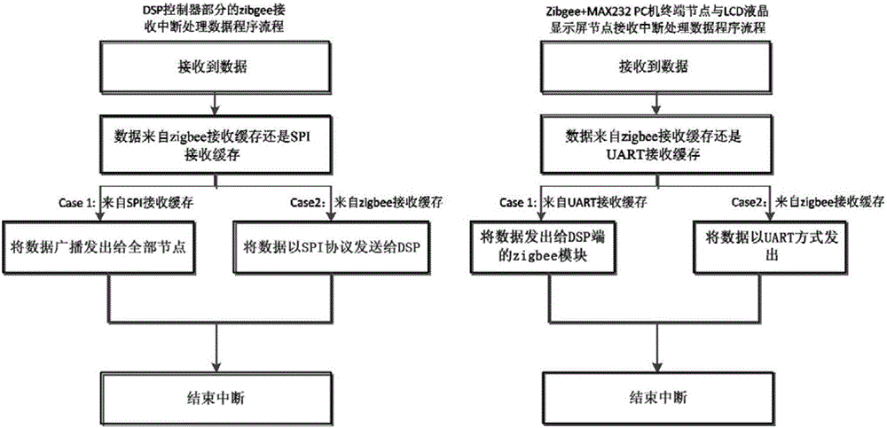

Image

  • Wireless multi-terminal motor debugging monitor based on zigbee and monitoring method of wireless multi-terminal motor debugging monitor
  • Wireless multi-terminal motor debugging monitor based on zigbee and monitoring method of wireless multi-terminal motor debugging monitor

Examples


Embodiment Construction

[0021] The present invention will be further described below in conjunction with accompanying drawing, and the structure and principle of this device are very clear to those skilled in the art. It should be understood that the specific embodiments described here are only used to explain the present invention, not to limit the present invention.

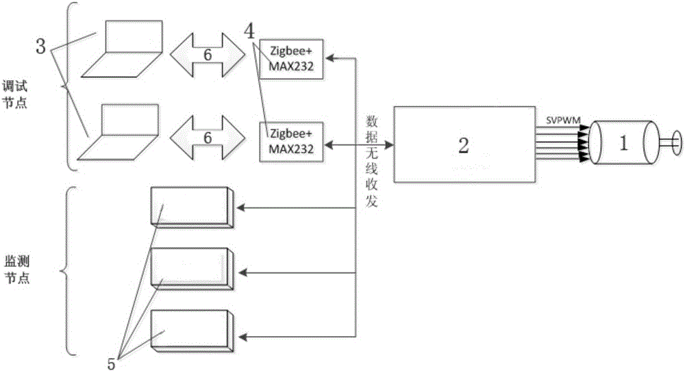
[0022] Such as figure 1 As shown, the system consists of motor, DSP controller with zigbee module, signal processor with zigbee module, PC, zigbee chip + max232 node module, LCD liquid crystal module, etc. The motor is connected with DSP controller and signal processor, each PC is connected with a zigbee chip + max232 node module, and a zigbee chip is solidified in the internal PCB circuit of each LCD liquid crystal module.

[0023] The zigbee chip of the DSP controller or the zigbee chip inside the signal processor work in the coordinator mode to form the zigbee coordinator module. The zigbee chip + max232 of the PC and the zigbee ...


PUM


Abstract

The invention relates to the technical field of motor terminal debugging monitors, in particular to a zigbee-based wireless multi-terminal motor debugging monitor and a monitoring method thereof. The motor is connected with a DSP controller and a signal processor and has a zigbee chip, a servo driver and a signal processor. A zigbee chip is solidified inside the LCD liquid crystal module for data transmission. After receiving the data, the zigbee chip of the PC transfers the data to the max232 interface through the serial port and then sends it to the PC via USB. The zigbee chip of the LCD liquid crystal module transmits the data after receiving the data. Send it to the LCD main control chip, and finally display it on the LCD screen through the GUI. The invention overcomes the deficiencies and potential safety hazards in the debugging and monitoring of the motor, reduces the risk factor in the debugging process and the possible problems in the monitoring link, can cooperate with multiple people, and can debug synchronously, and can save the trouble of communication connection lines. And it is a wireless multi-terminal motor debugging monitor that can monitor simultaneously with multiple monitoring platforms such as PC and LCD operation interface, and timely feedback problems.

Description

[technical field] [0001] The invention relates to the technical field of motor terminal debugging monitors, in particular to a device and method for simultaneously receiving, debugging and sending motor parameters by using wireless multi-terminals and multi-interfaces during the motor debugging process. [Background technique] [0002] The debugging and monitoring system of the servo motor is an important part of the servo system. A good debugging and monitoring system can efficiently complete the debugging of the motor, make it put into application as soon as possible, and can monitor the stability of each operation link in time. Feedback the problem in a timely manner. [0003] The current motor debugging and monitors are independently developed by major servo drive companies. The debugging monitors designed by each company include the host computer software installed on the PC or the operating system in a specific LCD liquid crystal display. Part of the debug communicatio...

Claims


Application Information

Patent Timeline
IPC IPC(8): G08C17/02
CPCG08C17/02
Inventor 王爽孙承波付俊永冯坚栋
Owner 上海新源工业控制技术有限公司
Learn More