Switch structure and explosion-proof device
A technology of switch structure and switch bracket, which is applied in the direction of electric switch, permanent magnet reed switch, magnetic/electric field switch, etc., to achieve the effect of reducing the distance
- Summary
- Abstract
- Description
- Claims
- Application Information
AI Technical Summary
Problems solved by technology
Method used
Image
Examples
Embodiment 1
[0031] [Example 1: Switch structure]
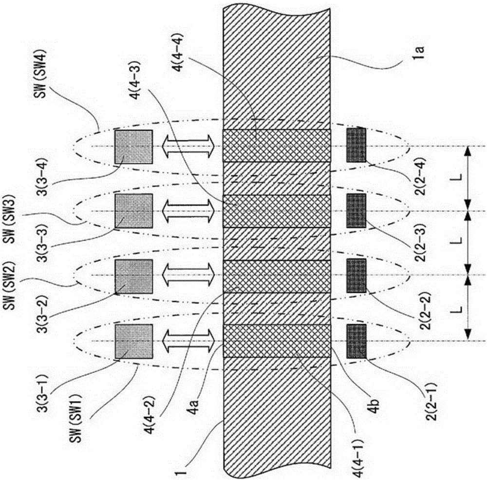
[0032] figure 1 It is a diagram showing main parts of an embodiment (Embodiment 1) of the switch structure according to the present invention. In this figure, 1 is an explosion-proof container, 2 is a magnetic sensor disposed inside the explosion-proof container 1, 3 is a magnet that generates a magnetic field, and the container wall 1a that isolates the inside and outside of the explosion-proof container 1 is a non-magnetic body. In addition, the magnet 3 is provided on the outside of the explosion-proof container 1 so as to be able to move forward and backward corresponding to the magnetic sensor 2 . It should be noted that in the explosion-proof container 1, although not shown in the figure, circuits and electronic components to be protected are housed.
[0033] In this switch structure, in the container wall (non-magnetic body) 1a between the magnetic sensors 2-1 to 2-4 and the magnets 3-1 to 3-4, corresponding to the magnetic sens...
Embodiment 2
[0040] [Example 2: Explosion-proof equipment]
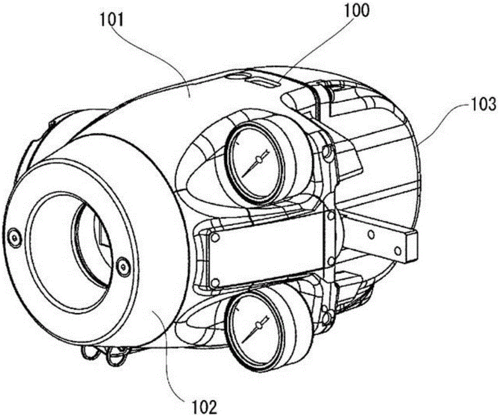
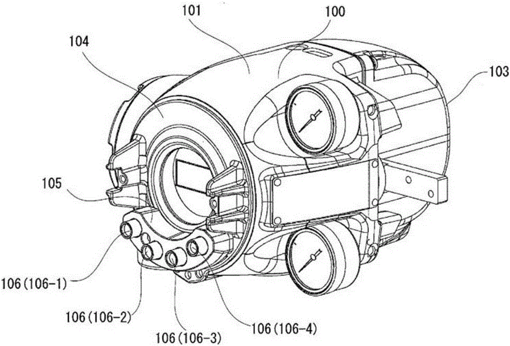
[0041] figure 2 It is an external perspective view showing an example (Example 2) of an explosion-proof device having a switch structure according to the present invention. exist figure 2 , shows a positioner that controls the opening of an air-operated regulating valve (valve) as a type of explosion-proof equipment. In the positioner, in order to be able to use it in an explosive gas atmosphere, it is necessary to have sufficient explosion-proof performance according to explosion-proof standards.
[0042] Figure 4 A block diagram of the internal structure of the positioner 100 is shown in . In this figure, 11 is an I / F (interface) terminal; 12 is a circuit module having a CPU (Central Processing Unit: central processing unit) and memory, etc.; 13 is an electro-pneumatic converter; The nozzle back pressure P of device 13 N Amplified as the output air pressure P out 15 is an angle sensor, which detects the operating posi...
PUM
 Abstract
Description
Claims
Application Information
 - R&D Engineer
- R&D Manager
- IP Professional
- Industry Leading Data Capabilities
- Powerful AI technology
- Patent DNA Extraction
Browse by: Latest US Patents, China's latest patents, Technical Efficacy Thesaurus, Application Domain, Technology Topic, Popular Technical Reports.
© 2024 PatSnap. All rights reserved.Legal|Privacy policy|Modern Slavery Act Transparency Statement|Sitemap|About US| Contact US: help@patsnap.com


