
Three-duct vertical take-off and landing flying car

A technology for vertical take-off and landing and flying car, which can be used in the direction of a car that can be converted into an airplane, which can solve the problems of poor stability, large rotor volume and complex folding structure, so as to improve safety and stability, flight stability and safety, and strengthen attitude control. Effect

Active Publication Date: 2019-03-22
NANJING UNIV OF AERONAUTICS & ASTRONAUTICS
View PDF2 Cites 0 Cited by
  • Summary
  • Abstract
  • Description
  • Claims
  • Application Information

AI Technical Summary

Problems solved by technology

Its disadvantage is that the rotor is large in size and exceeds the width of the vehicle by a lot, so it cannot be driven on the road. The second is that it lacks tail control compared with helicopters, the flight attitude is not easy to adjust, and the stability is poor.
[0005] 2. On the left and right sides of the body, use the rotors or ducted fans hanging on both sides of the foldable fixed wing as the power for take-off and flight, such as the Chinese patent application number 201310345157.3, but the fixed wing needs to be folded The road or the fan are folded onto the body, the folding structure is too complicated

Method used


Image

  • Three-duct vertical take-off and landing flying car
  • Three-duct vertical take-off and landing flying car
  • Three-duct vertical take-off and landing flying car

Examples


Embodiment Construction

[0021] The present invention will be further described below in conjunction with accompanying drawing.

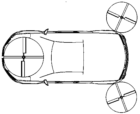
[0022] The structure of the present invention is as figure 1 and figure 2 As shown, the front of the body is equipped with a main duct lift fan that runs through the body, the power unit and the driving device are installed at the bottom of the body, and the folded first auxiliary duct lift fan and the second auxiliary duct lift fan are installed at the rear of the body. Fan, when working, two secondary duct lift fans are deployed to both sides of the vehicle body and are located on the same horizontal plane.

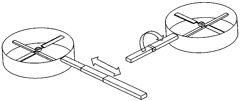
[0023] The connection structure between the auxiliary duct lift fan and the vehicle body is as follows: image 3 As shown, the first auxiliary ducted lift fan is connected to the vehicle body through a telescopic rod, and the second auxiliary ducted lift fan is connected to the vehicle body through a flip rod. When folded, the two auxiliary ducted lift fans overla...


PUM


Abstract

The invention provides a three-duct aerocar with a vertical take-off and landing function. The aerocar comprises a car body. A main duct lift fan penetrating through the car body is mounted on the front portion of the car body. A power device and a driving device are mounted at the bottom of the car body, and a foldable first auxiliary duct lift fan and a foldable second auxiliary duct lift fan are mounted on the rear portion of the car body. During work, the two auxiliary duct lift fans are unfolded to the two sides of the car body and located on the same horizontal plane. The three-duct aerocar can safely run on the ground like automobiles and also can fly in a vertical take-off and landing mode, influence on surrounding vehicles is avoided, and the three-duct aerocar is economical, safe and practical and meets aviation airworthiness and rules of road traffic relevant laws and regulations.

Description

technical field [0001] The invention relates to the field of ground-air amphibious vehicles, in particular to a three-duct vertical take-off and landing flying vehicle. Background technique [0002] Flying cars have been developed abroad for many years, most of which require an airport runway for takeoff and landing, and are relatively poor in practicability (such as the first generation of flying car product TRANSITION designed by TERRAFUGIA in Massachusetts and AEROMOBILE in Europe). The vertical take-off and landing flying car has also been trial-produced for many years in the world. For example, the MOLLER SKYCAR of MOLLER International Company in California, USA has good vertical take-off and landing function and flight performance, but its land performance is very poor, and it can only be used on very poor road conditions. Driving on a good road can only be regarded as a special general aircraft, but it cannot be called a real flying car. Due to the complex structural...

Claims


Application Information

Patent Timeline
Patent Type & Authority Patents(China)
IPC IPC(8): B60F5/02
CPCB60F5/02
Inventor 李小光朱清华
Owner NANJING UNIV OF AERONAUTICS & ASTRONAUTICS
Learn More