
Reinforced structure of hinges on the a-pillar of the body

A technology for strengthening structures and pillars, applied to superstructures, subassemblies of superstructures, vehicle components, etc., can solve problems that affect the life safety of occupants in the vehicle, large displacement of the doors, and inability to open the doors, so as to reduce the failure of opening Risk, safety protection, and improvement of the effect of car door drop

Active Publication Date: 2018-03-02
CHONGQING CHANGAN AUTOMOBILE CO LTD
View PDF7 Cites 0 Cited by
  • Summary
  • Abstract
  • Description
  • Claims
  • Application Information

AI Technical Summary

Problems solved by technology

However, in the frontal crash test and actual use of the car, the door frame was seriously deformed due to the insufficient strength of the upper part of the A-pillar, which caused the door to move too far behind the car, resulting in the door being unable to open and seriously affecting the safety of the occupants in the car. The existing upper structure of the A-pillar can no longer meet the increasingly stringent regulatory requirements. In addition, the upper part of the A-pillar is used for the installation of the door hinges, which requires sufficient joint stiffness and structural strength to ensure that the drop of the door meets the requirements.

Method used


Image

  • Reinforced structure of hinges on the a-pillar of the body
  • Reinforced structure of hinges on the a-pillar of the body
  • Reinforced structure of hinges on the a-pillar of the body

Examples


Embodiment Construction

[0024] In order to further explain the technical solution of the present invention, the present invention will be described in detail below in conjunction with the accompanying drawings.

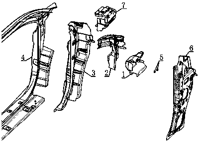
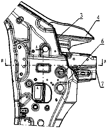
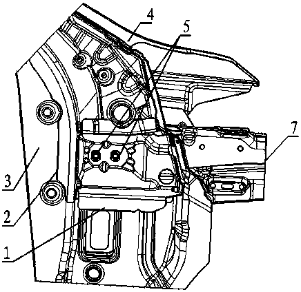
[0025] see Figure 1 to Figure 11 As shown, the A-pillar upper hinge reinforcement structure includes A-pillar upper reinforcement 2, A-pillar lower reinforcement 3, A-pillar upper hinge reinforcement 1, side wall outer panel 4, A-pillar inner panel 6 and side wall reinforcement Front connecting plate assembly 7. A column upper hinge reinforcement 1 includes a bottom plate and a top plate located above the bottom plate, the outer side of the bottom plate and the outer side of the top plate are connected by an outer side wall plate, and the middle part of the outer side wall plate bulges outward to form a first raised structure 11. A triangular rib is provided at the connection between the outer end surface of a protruding structure 11 and the side wall of the first protruding structure, an ...


PUM


Abstract

The invention discloses a column A upper hinge reinforcing structure for a vehicle body. The structure comprises a column A upper reinforcing piece, a column A lower reinforcing piece, a column A upper hinge reinforcing piece, a side wall outer board, a column A inner board and a side wall reinforcing piece front connecting board assembly. Four layers of metal plates of the end face of the outer end of the column A upper hinge reinforcing piece, the end face of the outer end of the column A upper reinforcing piece, the end face of the outer end of the column A lower reinforcing piece and the side wall outer board are in threaded connection together. An upper folded edge and a lower folded edge of the column A upper hinge reinforcing piece are welded to the column A inner board. A front folded edge of the column A upper hinge reinforcing piece is in lap joint with the front side face of the column A lower reinforcing piece and the rear end face of the side wall reinforcing piece front connecting board assembly in a point welding manner. A rear folded edge of the column A upper hinge reinforcing piece, the rear side face of the column A upper reinforcing piece and the rear side face of the column A lower reinforcing piece are welded in three layers. By the adoption of the column A upper hinge reinforcing structure, the strength high enough is guaranteed in a collision, the displacement of a vehicle door towards the rear position of a vehicle is effectively reduced, energy is transmitted and dispersed in time, and the requirement for the falling amount of door hinges in installation is met.

Description

technical field [0001] The invention relates to an automobile body structure, and more specifically relates to a hinge reinforcement structure on an A-pillar of a vehicle body. Background technique [0002] With the development of automobile technology and the rapid growth of vehicle ownership, people have higher and higher requirements for the safety performance and body quality of vehicles, requiring them to be able to withstand strict frontal and offset collisions, so that the safety of drivers and passengers can be improved. However, in frontal collisions, due to the limited space for energy-absorbing buffers, the requirements for body strength are relatively high. In terms of ensuring the quality of the body, the requirements for dropping the doors are becoming more and more stringent. [0003] The hinge reinforcement on the A-pillar of the car body is an important part of the car body skeleton. It must have excellent passive safety and a reasonable transmission path of...

Claims


Application Information

Patent Timeline
Patent Type & Authority Patents(China)
IPC IPC(8): B62D25/04
CPCB62D25/04
Inventor 曾俊倪春燕戴路陈强强刘敛杰
Owner CHONGQING CHANGAN AUTOMOBILE CO LTD
Learn More