Method for reinforcing railway through piling girders combined with I-steel cross girders

A technology of I-beams and beams, which is applied in the direction of roads, laying tracks, tracks, etc., can solve problems such as slope instability and collapse, endangering driving safety, and difficult control of the scope of railway subgrade collapse, so as to enhance integrity and improve construction efficiency , Reduce the effect of structural technical risk and construction risk

Inactive Publication Date: 2016-07-06
SHENYANG RAILWAY SURVEY DESIGN CONSULTING CO LTD
View PDF3 Cites 6 Cited by
  • Summary
  • Abstract
  • Description
  • Claims
  • Application Information

AI Technical Summary

Problems solved by technology

[0003] In order to solve the above-mentioned technical problems, the present invention provides a method for reinforcing the railway with pile-row beams combined with I-beam beams, that is, the combined structure of pile-row beams combined with I-beam beams is used for line reinforcement, and rail buckle beams are used to reinforce the railway. The vertical connection of the beams of beams strengthens the integrity of the beams of I-beams. This form of line reinforcement enables the railway load within the scope of subgrade collapse of the line to be effectively transmitted to the pile-row beam structure through the beams of I-beams, which solves the problem of using the traditional When the vertical and horizontal beam lifting method is used to strengthen the oblique wide bridge structure with high subgrade, the collapse range of the railway subgrade is not easy to control, and the exposure time of the line within the collapse range is too long, which may easily cause slope instability and collapse, endangering traffic safety and other problems

Method used


Image

  • Method for reinforcing railway through piling girders combined with I-steel cross girders
  • Method for reinforcing railway through piling girders combined with I-steel cross girders
  • Method for reinforcing railway through piling girders combined with I-steel cross girders

Examples


Embodiment Construction

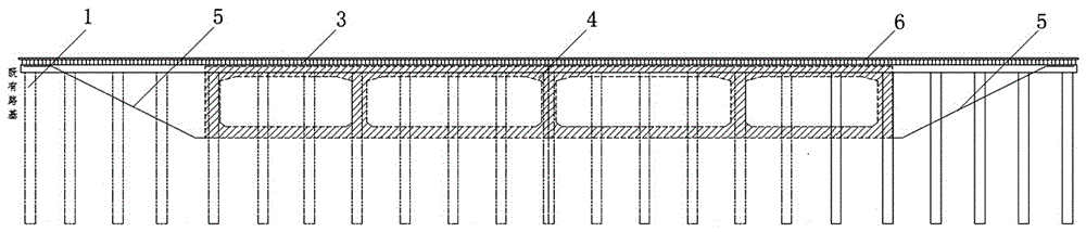
[0022] The method for reinforcing the railway with row pile beams combined with I-beam beams, the steps are:

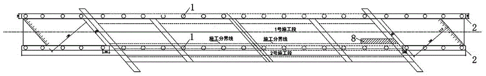
[0023] 1) Reinforcement of the structural foundation: On both sides of the construction entrance line, a row of bored piles 1 are used as the reinforcement foundation, and at the top of each row of bored piles 1, a pile top crown beam 2 is arranged along the direction of the arrangement of the bored piles 1 , the bolts connected with the I-beam beam 3 are reserved on the pile top crown beam 2, and the g grid structure size is determined by the specific structural conditions during construction.

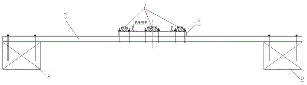
[0024] 2) Lay buckle rail beams: carry out conventional stress relief and long rail relaxation on the line during the train skylight time, replace the sleepers 6, replace the concrete sleepers with wooden sleepers, and lay the buckle rail beams 7 on the sleepers 6, as described The buckle rail beam 7 is specifically a 3-5-3 buckle rail beam composed of 43kg / m rails.

[0025]...


PUM


Abstract

The invention creatively provides a method for reinforcing a railway through piling girders combined with I-steel cross girders, namely line reinforcement is performed in the form of a combined structure of the piling girders combined with I-steel cross girders, besides, longitudinal connection of the I-steel cross girders is performed through rail girders, the completeness of the I-steel cross girders is strengthened, and the line reinforcing form enables railway load within a range of line roadbed earthfall to be effectively transmitted to a piling girder structure through the I-steel cross girders. Lines are reinforced by the method disclosed by the invention, construction can be performed through a conventional cast-in-situ construction technology below the lines, so that the construction cost is reduced, the construction efficiency is improved, the structural technique risk and the construction risk are reduced, and economic benefits and social benefits are good; a series of problems that the earthfall range of railway roadbeds is not liable to control, the exposure time of the lines within the earthfall range is too long, destabilization and collapse of slopes are easy to cause, and driving safety is endangered, which are generated when high-roadbed skew-intersection wide bridge structures are reinforced by a conventional longitudinal and horizontal girder lifting method, are solved.

Description

technical field [0001] The invention belongs to the field of civil engineering construction, and mainly relates to a method for reinforcing a railway with row pile beams combined with I-shaped steel beams. Background technique [0002] In recent years, with the acceleration of the urbanization process, the urban population is increasing day by day, and the urban traffic volume is increasing in series. Considering the urban development, the urban roads are getting wider and wider. Because the underpass interchange can save land and cost, and It has less impact on the surrounding existing buildings (such as lighting, etc.), and has irreplaceable advantages in urban road construction. The road and rail crossings are not the same. When the oblique angle of the bridge body is large, the filling soil of the railway subgrade is high, the geological conditions are poor, and the total transverse width of the frame bridge is wider than the conventional width, it is not possible to us...

Claims


Application Information

Patent Timeline
Patent Type & Authority Applications(China)
IPC IPC(8): E01B2/00E01B29/06
CPCE01B2/00E01B29/06
Inventor 臧立秋金勇赵志文周路舟
Owner SHENYANG RAILWAY SURVEY DESIGN CONSULTING CO LTD
Why Eureka
Try Eureka