A frame barrel wharf structure and its manufacturing method

A wharf and frame barrel technology, which is applied in the field of frame barrel wharf structure and manufacturing, can solve problems such as project investment waste, and achieve the effects of reducing project cost, saving pile foundation costs, and reducing construction costs

Active Publication Date: 2019-04-02
CCCC THIRD HARBOR CONSULTANTS
View PDF7 Cites 0 Cited by
  • Summary
  • Abstract
  • Description
  • Claims
  • Application Information

AI Technical Summary

Problems solved by technology

For the shallow draft of the workboat wharf, this construction method is also adopted, which will cause waste of project investment

Method used


Image

  • A frame barrel wharf structure and its manufacturing method
  • A frame barrel wharf structure and its manufacturing method

Examples


Embodiment 1

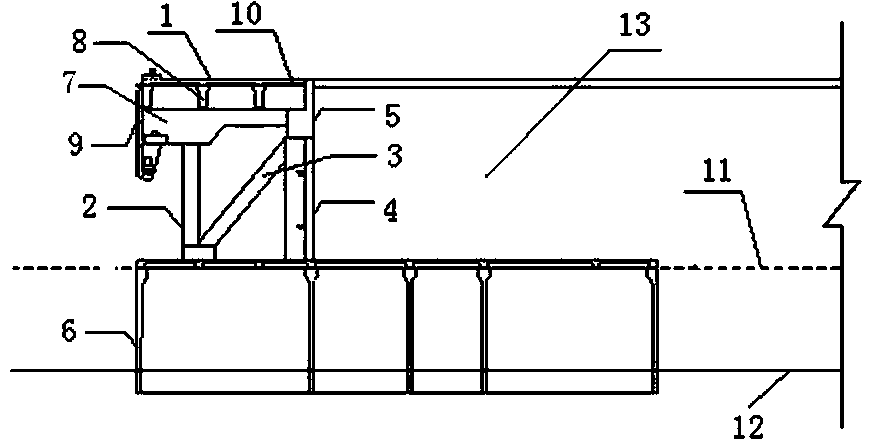
[0031] Such as figure 1 As shown, a frame barrel wharf structure is composed of an upper wharf structure 1, a basic barrel body 6, a frame column 2, a diagonal brace 3, a retaining wall 4 and an upper guide beam 5; the upper wharf structure 1 is composed of Composed of beams 7, longitudinal beams 8 and wharf panels 10, longitudinal beams 8 are arranged above the beams 7, and wharf panels 10 are arranged above the longitudinal beams 8; the upper wharf structure 1 mainly bears the berthing load and transmits it to the foundation barrel 6. Realize the function of the wharf; the upper guide beam 5 connects the upper wharf structure 1 with the retaining wall 4, and transfers the load of the wharf to the retaining wall 4 and the rear soil 13, and also has the function of retaining soil; the frame column 2 The upper end is connected to the beam 7, and the lower end of the frame column 2 is connected to the foundation barrel body 6, and the frame column 2 transfers the load of the upp...

Embodiment 2

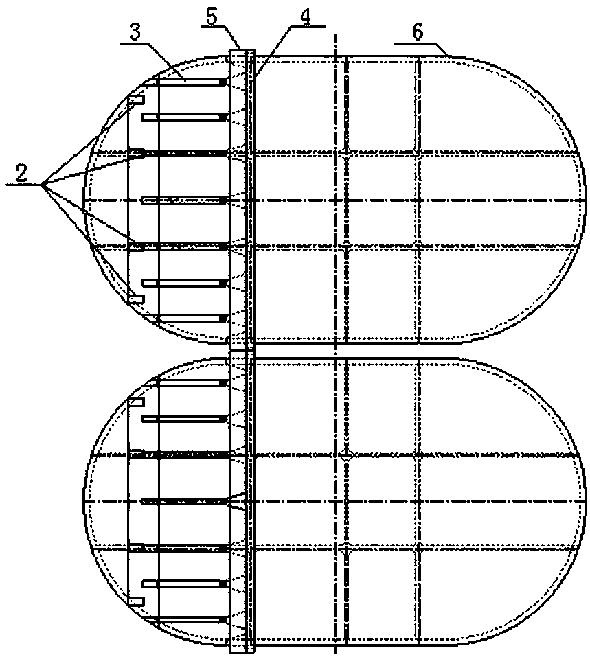
[0033] Such as Figure 1-2 As shown, a method for manufacturing a frame barrel wharf structure, the frame barrel wharf structure is composed of an upper wharf structure 1, a base barrel body 6, a frame column 2, a diagonal brace 3, a retaining wall 4 and an upper guide beam 5; Its manufacturing method is as follows:

[0034] 1) Prefabricated foundation barrel 6, frame column 2, diagonal brace 3, retaining wall 4;

[0035] 2) Install the foundation barrel 6; install the frame column 2 and the retaining wall 4 above the foundation barrel 6, and the diagonal brace 3 connects the frame column 2 and the retaining wall 4;

[0036] 3) cast-in-place upper guide beam 5;

[0037] 4) Foundation treatment of land reclamation and soil behind dredging reclamation;

[0038] 5) The beam 7 of the cast-in-place upper wharf structure 1;

[0039] 6) installing the longitudinal beam 8 and the cast-in-place node;

[0040] 7) Installation of berthing components and fender attachments;

[0041]...


PUM


Abstract

The invention discloses a frame barrel wharf structure. The structure consists of an upper wharf structure, a basic barrel body, a frame column, an inclined support rod, a retaining wall and an upper guide beam; the upper wharf structure consists of a cross beam, a longitudinal beam and a wharf panel; the longitudinal beam is arranged above the cross beam; the wharf panel is arranged above the longitudinal beam; the upper guide beam connects the upper wharf structure with the retaining wall on the lower side; the upper end of the frame column is connected with the cross beam, and the lower end of the frame column is connected with the basic barrel body; the basic barrel body mainly bears the horizontal soil pressure generated by rear sludge reclamation and the parking load transferred by the upper wharf structure, and is combined with the retaining wall to form a upright quay wall to realize a retaining function; the right end of the inclined support rod is connected with the retaining wall; and the left end of the inclined support rod is connected with the basic barrel body. The invention further discloses a manufacturing method of the frame barrel wharf structure. Compared with a conventional wharf, the frame barrel wharf structure saves the pile foundation cost, prevents the water construction, realizes the land area construction, reduces the construction cost, and reduces the construction cost.

Description

technical field [0001] The invention relates to a port wharf structure, in particular to a barrel wharf structure and a manufacturing method. Background technique [0002] The dug-in harbor basins on muddy coasts mostly use slope dikes as soil retaining cofferdams, and connect high-pile beam-slab wharves through approach bridges to realize berthing functions. For the shallow draft of the workboat wharf, this construction method is also adopted, which will cause a waste of engineering investment. In recent years, the barrel structure has been used as a wall structure on muddy coasts, which can provide vertical walls for dug-in harbor basins and replace slope dikes to achieve soil retaining functions. If the superstructure can be modified to realize the berthing function, a large amount of engineering investment can be saved. Invent a kind of frame barrel wharf structure that can solve the dual functions of retaining soil and berthing for this reason. Contents of the inven...

Claims


Application Information

Patent Timeline
Patent Type & Authority Patents(China)
IPC IPC(8): E02B3/06
CPCE02B3/06
Inventor 李武程泽坤
Owner CCCC THIRD HARBOR CONSULTANTS
Why Eureka
Try Eureka