Concrete bearing platform used for steel-structure stand column

A technology for concrete and steel structures, applied in basic structure engineering, building structure, construction, etc., can solve the problems of increasing construction difficulty of concrete caps, difficulty in installing holes for column chassis, and time-consuming, saving manpower and construction process. Fast, load-bearing strength-enhancing effects

Inactive Publication Date: 2016-07-06
徐州途远精密设备有限公司
View PDF0 Cites 0 Cited by
  • Summary
  • Abstract
  • Description
  • Claims
  • Application Information

AI Technical Summary

Problems solved by technology

[0002] In the field of steel structures, it is often necessary to use concrete caps to fix steel structure columns during construction. This kind of concrete caps needs to fix multiple screws. The existing concrete caps are easy to shift the screws during pouring, which leads to It is difficult to align the mounting holes of the column chassis with each screw rod
Some existing concrete caps use reinforcement cages and screws to cooperate with each other to prevent displacement. However, the assembly of such reinforcement cages requires a lot of man-hours, which increases the difficulty of construction for concrete caps.

Method used


Image

  • Concrete bearing platform used for steel-structure stand column
  • Concrete bearing platform used for steel-structure stand column
  • Concrete bearing platform used for steel-structure stand column

Examples


Embodiment Construction

[0012] The present invention will be further described below in conjunction with accompanying drawing.

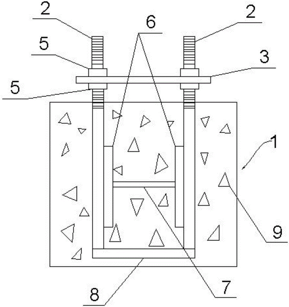
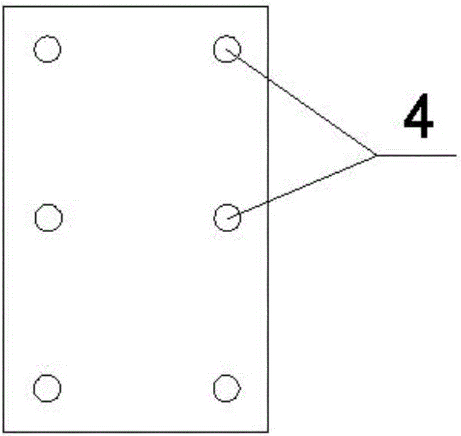
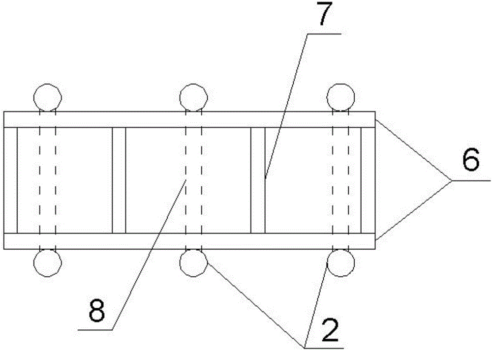
[0013] Such as Figure 1 to Figure 3 As shown, a concrete cap for a steel structure column includes a cap body 1, two rows of screw rods 2 evenly distributed along the length direction of the cap body 1, a horizontal steel sleeve plate 3, and two vertically arranged Longitudinal pressure bearing plate 6, the upper end of the screw rod 2 protrudes from the top surface of the platform body 1, and its lower part is anchored in the platform body 1, the steel sleeve plate 3 is provided with a plurality of positioning holes 4, each positioning The holes 4 are in one-to-one correspondence with the screw rods 2 of the platform body 1, and each screw rod 2 passes through the corresponding positioning hole 4 on the steel sleeve plate 3. The nut 5, the top surface and the bottom surface of the steel sleeve plate 3 abut against the adjusting nuts 5 on both sides respectively, and the ...


PUM


Abstract

A concrete cap for a steel structure column, comprising a cap body, two rows of screw rods uniformly distributed along the length direction of the cap body, a horizontal steel sleeve plate, and two vertically arranged longitudinal pressure bearing plates, the The upper end of the screw protrudes from the top surface of the cap body, and its lower part is anchored in the cap body. The steel sleeve plate is provided with a plurality of positioning holes, and each positioning hole corresponds to the screw rod of the cap body. The screw rod passes through the corresponding positioning hole on the steel sleeve plate, and each screw rod is screwed with an adjusting nut on both sides of the steel sleeve plate. A longitudinal pressure-bearing plate is arranged on the inside of the two rows of screws, and the inside of the two rows of screws are connected to the outer sides of the two longitudinal pressure-bearing plates by spot welding, and a plurality of horizontal pressure-bearing plates are arranged at intervals between the two longitudinal pressure-bearing plates. connecting rod A. The concrete cap has simple structure and high load-bearing strength, and can ensure that the screw rod will not be displaced during the concrete pouring process.

Description

technical field [0001] The invention relates to the field of steel structures, in particular to a concrete cap used for steel structure columns. Background technique [0002] In the field of steel structures, it is often necessary to use concrete caps to fix steel structure columns during construction. This kind of concrete caps needs to fix multiple screws. The existing concrete caps are easy to shift the screws during pouring, which leads to It is difficult to align the mounting holes of the column chassis with the respective screw rods. Some existing concrete caps use reinforcement cages to cooperate with screws to prevent displacement. However, the assembly of such reinforcement cages requires a lot of man-hours, which increases the difficulty of construction for concrete caps. Contents of the invention [0003] Aiming at the above-mentioned problems in the prior art, the present invention provides a concrete cap for a steel structure column. The concrete cap has a si...

Claims


Application Information

Patent Timeline
IPC IPC(8): E02D27/42
CPCE02D27/42E04B2001/2463
Inventor 薛茹丹
Owner 徐州途远精密设备有限公司
Why Eureka
Try Eureka