Cooling platform for gate valve casting

A technology for cooling platform and gate valve, applied in the field of gate valve manufacturing, can solve the problems of low production efficiency, very long time consumption, etc., and achieve the effects of easy operation, rapid cooling and simple platform structure

Inactive Publication Date: 2018-09-28
芜湖市华邦流体科技有限公司
View PDF13 Cites 2 Cited by
  • Summary
  • Abstract
  • Description
  • Claims
  • Application Information

AI Technical Summary

Problems solved by technology

[0002] The gate valve production process often needs to be manufactured by casting process. During casting, the metal liquid is injected into the casting mold. After the metal liquid is cooled and formed in the casting mold, a solidified gate valve blank is obtained. The gate valve is obtained after the blank is taken out for finishing. For the finished product, in order to take out the solidified gate valve blank from the sand box, it is usually necessary to wait for the gate valve blank and the sand box to cool to a certain temperature before performing the demoulding operation. It will take a very long time to wait for the sand box and the blank to cool naturally , leading to low production efficiency

Method used


Image

  • Cooling platform for gate valve casting
  • Cooling platform for gate valve casting
  • Cooling platform for gate valve casting

Examples


Embodiment Construction

[0016] Preferred embodiments of the present invention will be described in detail below in conjunction with the accompanying drawings.

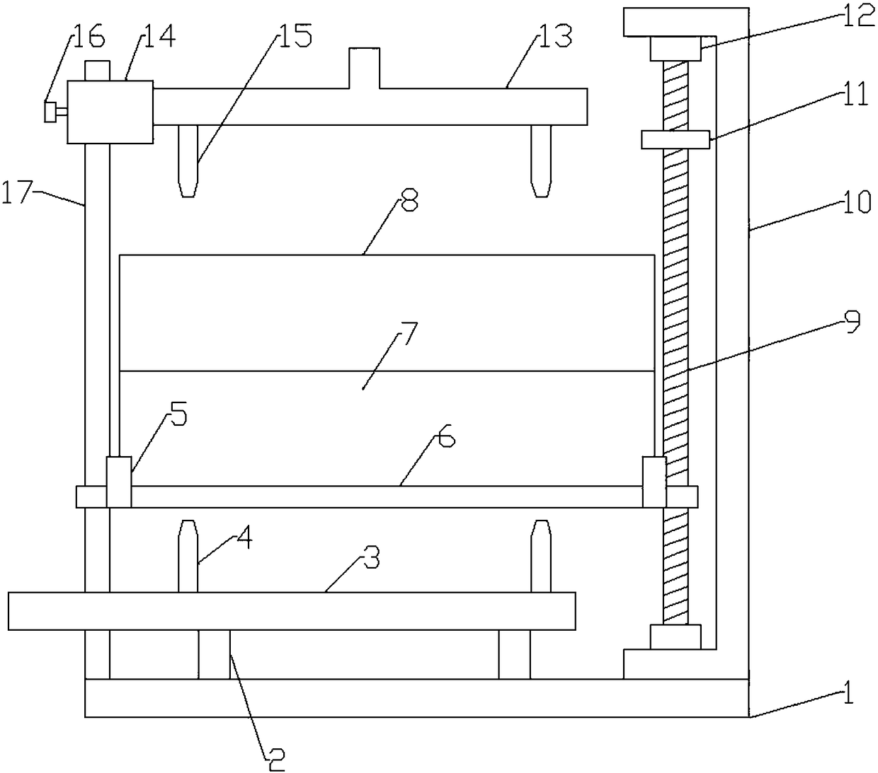
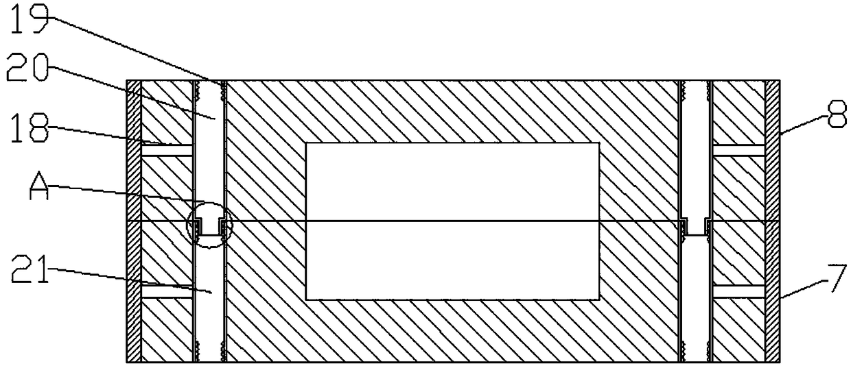
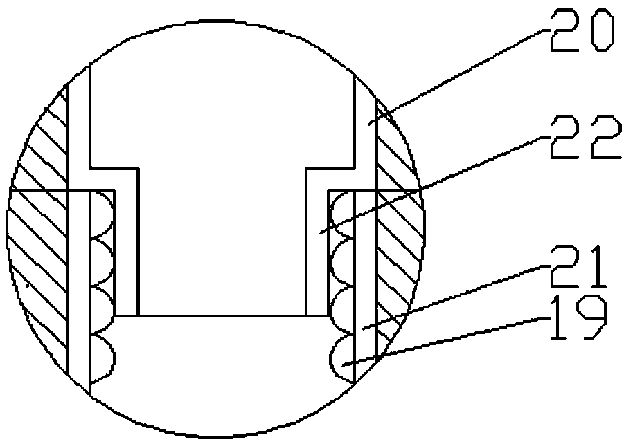
[0017] Figure 1-4 A specific embodiment of the present invention is shown: a cooling platform for gate valve casting, including a bottom plate 1, a C-shaped frame 10 and a slide bar 17 are provided at both ends of the bottom plate 1, and the upper and lower ends of the C-shaped frame 10 are provided with Screw mandrel base 12 is arranged, and screw mandrel 9 is arranged between described screw mandrel base 12, and described screw mandrel 9 is provided with the sand box frame 6 that thread connects, and the other end of described sand box frame 6 slides with slide bar 17 connection, the upper end of the sand box frame 6 is provided with a lower sand box 8 and an upper sand box 7, and the inner walls of both sides of the upper sand box 7 and the lower sand box 8 are provided with a plurality of evenly arranged connecting rods 18. One end of c...


PUM


Abstract

The invention discloses a cooling platform for gate valve casting. The cooling platform comprises a bottom plate. A C-shaped frame and a sliding rod are arranged at the two ends of the bottom plate. Lead screw bases are arranged at the upper end and the lower end of the C-shaped frame. A lead screw is arranged between the lead screw bases and provided with a threaded-connection sand box frame. Theupper end of the sand box frame is provided with a lower sand box and an upper sand box, and a plurality of evenly-arranged connecting rods are arranged on the inner walls of the two side faces of the upper sand box and the inner walls of the two side faces of the lower sand box. A first heat dissipation pipe is fixed to one ends of the connecting rods in the upper sand box, and a second heat dissipation pipe is fixed to one ends of the connecting rods in the lower sand box. The sliding rod is further provided with a sliding-connection sliding base. A locking bolt is arranged on the side faceof the sliding base. A water inlet main pipe is fixed to the sliding base, and the lower end of the water inlet main pipe communicates with a plurality of water inlet branch pipes. The middle portionof the bottom plate is further provided with a support, a water outlet main pipe is fixed to the upper end of the support, and the upper end of the water outlet main pipe communicates with a plurality of water outlet branch pipes. By means of the cooling platform, rapid gate valve casting sand box cooling can be achieved, the platform structure is simple, operation is easy, and the gate valve manufacturing efficiency is improved.

Description

technical field [0001] The invention relates to the field of gate valve manufacturing, in particular to a cooling platform for gate valve casting. Background technique [0002] The gate valve production process often needs to be manufactured by casting process. During casting, the metal liquid is injected into the casting mold. After the metal liquid is cooled and formed in the casting mold, a solidified gate valve blank is obtained. The gate valve is obtained after the blank is taken out for finishing. For the finished product, in order to take out the solidified gate valve blank from the sand box, it is usually necessary to wait for the gate valve blank and the sand box to cool to a certain temperature before performing the demoulding operation. It will take a very long time to wait for the sand box and the blank to cool naturally , leading to low production efficiency. Contents of the invention [0003] The technical problem to be solved by the present invention is to ...

Claims


Application Information

Patent Timeline
IPC IPC(8): B22D30/00
Inventor 俞立华吴桂林俞璐
Owner 芜湖市华邦流体科技有限公司
Why Eureka
Try Eureka