Pressure reduction throttling valve and application method

A technology of throttle valve and valve cavity, which is applied in the field of decompression and throttle valve, can solve the problems of complex structure, inability to close the valve, etc., and achieve the effect of improving spray effect, overcoming interference, and simple structure

Inactive Publication Date: 2016-07-06
SHANGHAI AOSHENG CLEANING TECH CO LTD
View PDF12 Cites 1 Cited by
  • Summary
  • Abstract
  • Description
  • Claims
  • Application Information

AI Technical Summary

Problems solved by technology

[0002] In the microporous atomization deodorization system, if the pressure of the infusion line is too high, it is easy to cause seepage and water leakage of the microporous atomization sheet, which will affect the atomization effect
[0003] Ordinary throttle valves use manual adjustment of the diameter to achieve throttling and decompression, but they cannot automatically adjust the diameter according to the pressure at the discharge end, nor can they be completely closed when the pressure at the discharge end reaches the rated value
[0004] Chinese patent announcement number CN103591317A discloses a throttle valve, which includes a cone, a valve stem, a pressure relief hole, a limiter, a spring, etc. The defect of using a spring is that the throttle valve cannot work normally at a lower pressure. Also cannot fully close the valve when the rated pressure is reached
However, the disadvantage of this technology is that the structure is complex and the atomization effect is not ideal

Method used


Image

  • Pressure reduction throttling valve and application method
  • Pressure reduction throttling valve and application method

Examples


Embodiment Construction

[0022] In order to describe the embodiments of the present invention more clearly, the present invention will be further described below in conjunction with the accompanying drawings.

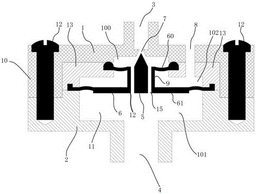
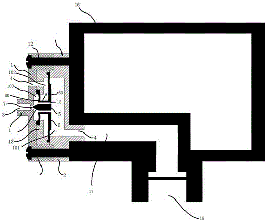
[0023] Such as figure 1 As shown, the embodiment of the present invention provides a pressure reducing throttle valve, which includes a valve body 10 and a valve core 12 , wherein the valve body 10 includes an upper valve body 1 , a lower valve body 2 and a middle valve body 13 . A valve cavity 11 is formed in the valve body 10, and the valve core 12 is arranged in the valve cavity 11. The valve cavity 11 includes a first valve cavity 100, a second valve cavity 101, and a third valve cavity 102. The valve core 12 includes a cone valve. Tip 5 and flexible diaphragm 6, flexible diaphragm 6 comprises upper flexible diaphragm 60 and lower flexible diaphragm 61 again, upper flexible diaphragm 60 and lower flexible diaphragm 61 are connected by valve stem 9, upper flexible diaphragm 60 and upper The...


PUM


Abstract

The invention relates to a pressure reducing and throttling valve, comprising a valve body (10), a liquid inlet (3) arranged at the upper end of the valve body (10), and a liquid inlet (3) arranged at the lower end of the valve body (10) and the liquid inlet (3). The liquid outlet (4) corresponding to the position is the conical valve tip (5) set in the cavity of the valve body (10), wherein the conical valve tip (5) is connected to the valve body through a flexible diaphragm (6) (10) Upper, the valve body (10) includes the upper valve body (1), the lower valve body (2), and the middle valve body (13). The beneficial effect is that the structure is simple, reliable and stable, and the flexible diaphragm (6) inherently Features Automatic adjustment of pressure and flow, suitable for synchronous working conditions of low pressure, discontinuous, small flow, and also suitable for high pressure delivery, but must work at a lower pressure with a small flow of large microporous atomization spray device, so that Overcome the interference caused by pressure fluctuations, improve the spray effect of the microporous spray atomization device, and prevent liquid leakage.

Description

technical field [0001] The present invention relates to a throttling valve, in particular to a pressure reducing throttle valve installed on a microporous atomization and spraying device, and at the same time, a method for using the pressure reducing throttle valve. Background technique [0002] In the microporous atomization deodorization system, if the pressure of the infusion line is too high, it is easy to cause seepage and water leakage of the microporous atomization sheet, which will affect the atomization effect. [0003] Ordinary throttle valves use manual adjustment of the diameter to achieve throttling and decompression, but they cannot automatically adjust the diameter according to the pressure at the discharge end, nor can they be completely closed when the pressure at the discharge end reaches the rated value. [0004] Chinese patent announcement number CN103591317A discloses a throttle valve, which includes a cone, a valve stem, a pressure relief hole, a limite...

Claims


Application Information

Patent Timeline
Patent Type & Authority Applications(China)
IPC IPC(8): F16K17/34F16K31/126
CPCF16K17/34F16K31/1268
Inventor 赵啸林
Owner SHANGHAI AOSHENG CLEANING TECH CO LTD
Why Eureka
Try Eureka