Centrifugal dehydration mechanism for cleaned straw

A cleaning and centrifugal technology, which is applied in the direction of drying solid materials, drying solid materials without heating, lighting and heating equipment, etc., can solve the problems of slow dehydration of straw, achieve fast dehydration speed, and shorten the time of dehydration and drying , The effect of speeding up the application production cycle

Inactive Publication Date: 2016-07-06
CHONGQING YONGYAO AGRI DEV
View PDF0 Cites 0 Cited by
  • Summary
  • Abstract
  • Description
  • Claims
  • Application Information

AI Technical Summary

Problems solved by technology

The dehydration and drying part currently used mainly relies on natural sunlight for drying. This method makes the dehydration of the straw very slow. If it needs to be in the case o

Method used


Image

  • Centrifugal dehydration mechanism for cleaned straw

Examples


Example Embodiment

[0021] Example 1

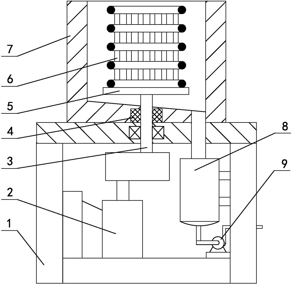
[0022] like figure 1 As shown in the figure, the centrifugal dewatering mechanism after straw cleaning includes a dewatering bucket 6 and a workbench 1. The workbench 1 is equipped with a moisture collection tank 7 for collecting the dehydrated straws uniformly, and a drainage line is arranged at the bottom of the moisture collection tank 7. A rotatable rotary disk 5 is arranged in the moisture collection tank 7, the dehydration bucket 6 is installed on the rotary disk 5, and a rotating shaft 3 is vertically fixed at the bottom of the rotary disk 5, and the corresponding rotating shaft 3 is respectively at the bottom of the moisture collection tank 7 and the working The table 1 is provided with a through hole for the rotating shaft 3 to pass through independently. The rotating shaft 3 is connected with the worktable 1 through a bearing in a mutual rotational fit. The lower part of the drainage pipeline is provided with a collection tank 8 and a delivery wat...

Example Embodiment

[0025] Embodiment 2

[0026] On the basis of the first embodiment, the sealing member 4 is a packing seal; the power mechanism is a hydraulic motor; the inclination angle of the inclined surface is changed to 20 degrees. Others are the same as the first embodiment.

Example Embodiment

[0027] Embodiment 3

[0028] On the basis of the first embodiment, the power mechanism is a pneumatic motor; the inclination angle of the inclined surface is changed to 15 degrees. Others are the same as the first embodiment.


PUM

PropertyMeasurementUnit
Angleaaaaaaaaaa

Abstract

The invention relates to a centrifugal dehydration mechanism for cleaned straw, and belongs to the technical field of dehydration. The centrifugal dehydration mechanism for the cleaned straw comprises a dehydration barrel and a worktable, wherein a water collecting tank used for collecting water from the dehydrated straw in a unified mode is installed on the worktable; a water drainage pipeline is arranged at the bottom of the water collecting tank; a rotary disc capable of rotating is arranged in the water collecting tank; the dehydration barrel is installed on the rotary disc; a rotary shaft is vertically fixed to the bottom of the rotary disc; through holes which allow the rotary shaft to independently penetrate through are formed in the bottom of the water collecting tank and the worktable correspondingly and correspond to the rotary shaft; the rotary shaft is connected with the worktable through a bearing in a mutual rotary matching mode; the rotary shaft is connected with the water collecting tank in a mutual rotary matching mode through a sealing part; and a collecting tank and a water conveying pump are arranged on the lower portion of the water drainage pipeline. The centrifugal dehydration mechanism for the cleaned straw is simple in structure, the cleaned straw is high in dehydration speed and generally can meet the dehydration requirement only in half of the day, the time for dehydrating and drying the straw is shortened effectively, and the application and production period of the straw is accelerated.

Description

technical field [0001] The invention relates to a centrifugal dehydration mechanism for straw cleaning, which belongs to the technical field of dehydration. Background technique [0002] At present, there are more and more crop straw utilization technologies. No matter what the technical application is, the straw needs to be cleaned first. The common process is: first collect the straw and cut it into segments, and then clean the cut segments. , and then dehydrate and dry the cleaned straw, and finally enter the straw application production link. The dehydration and drying part currently used mainly relies on natural sunlight for drying. This method makes the dehydration of the straw very slow. If it needs to be in the case of sufficient sunlight in summer, it will take about two days. In about five days, with the increasing application of straw, this dehydration method can no longer keep up with the demand. Contents of the invention [0003] According to the deficiencie...

Claims


Application Information

Patent Timeline
IPC IPC(8): F26B5/08F26B25/00
Inventor 王成华
Owner CHONGQING YONGYAO AGRI DEV
Why Eureka
Try Eureka