Fixture transfer plate for stern room vibration test

A technology of vibration test and adapter plate, applied in the field of adapter plate, can solve the problems such as the increase of the cost of the vibration test of the tail cabin, and achieve the effect of reducing the clamping and correction time, increasing the number of bolts, and ensuring the firmness and stability of the connection.

Inactive Publication Date: 2016-07-06
HARBIN JIANCHENG GRP
View PDF8 Cites 2 Cited by
  • Summary
  • Abstract
  • Description
  • Claims
  • Application Information

AI Technical Summary

Problems solved by technology

[0003] The purpose of the present invention is to solve the problem that the existing test fixture is only suitable for one size of the tail cabin structure, and when the tail cabin structure is similar and the weight is equal, but the size of the tail cabin does not match the size of the test fixture, a matching test is required Fixture, the problem of increasing the cost of the tail tank vibration test, providing a clamp adapter plate for the tail tank vibration test

Method used


Image

  • Fixture transfer plate for stern room vibration test
  • Fixture transfer plate for stern room vibration test
  • Fixture transfer plate for stern room vibration test

Examples


specific Embodiment approach 1

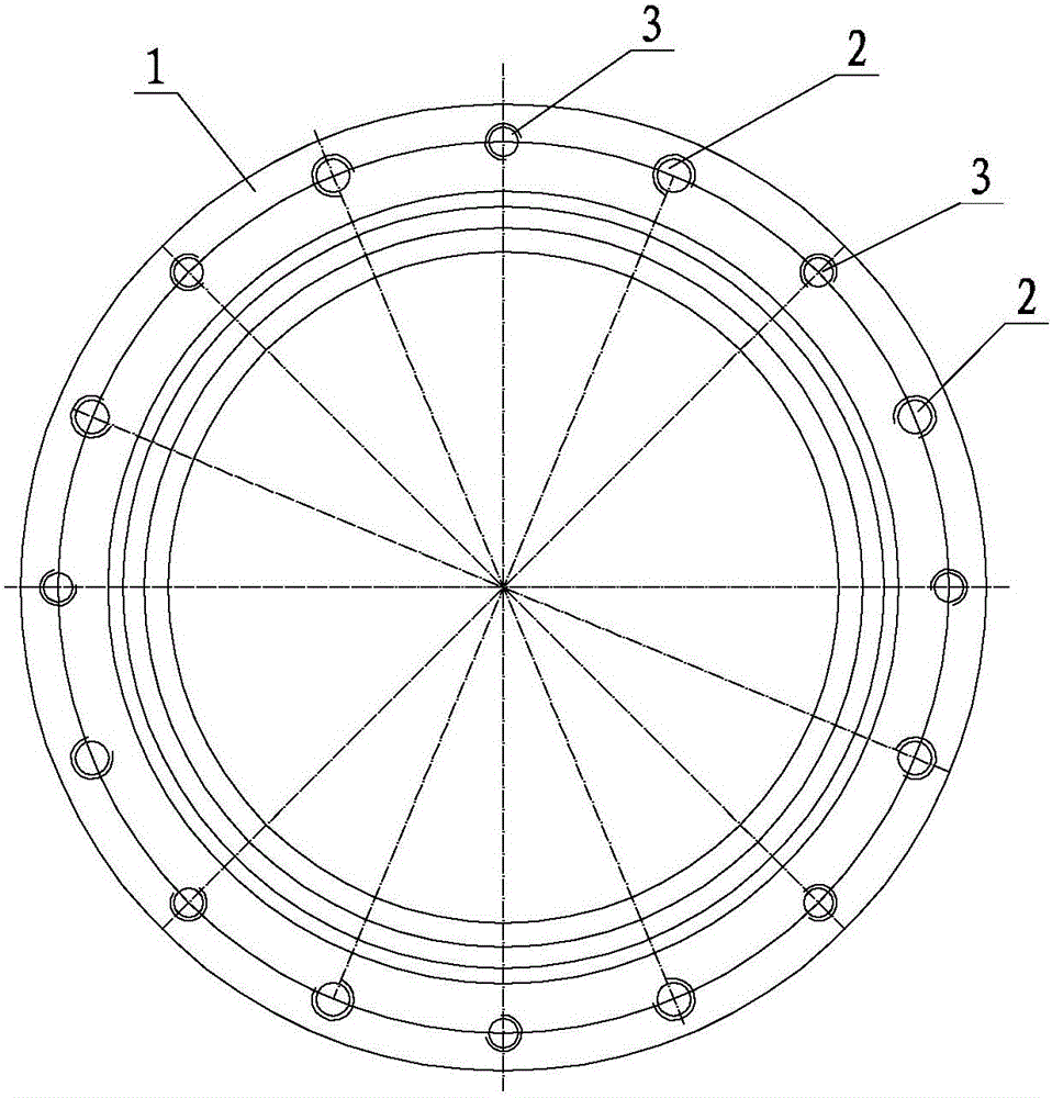
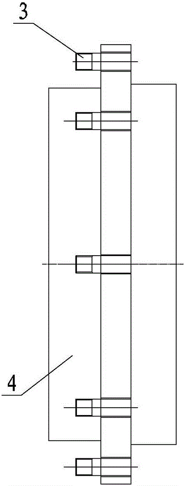
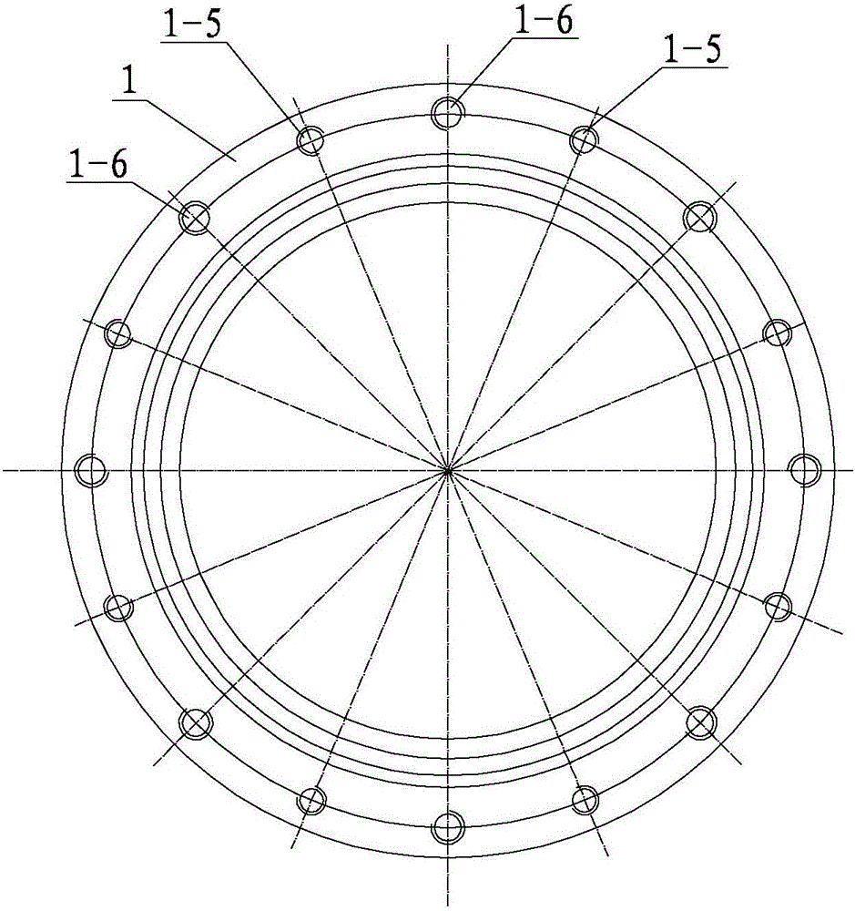
[0016] Specific implementation mode one: combine Figure 1 to Figure 6 Describe this embodiment. This embodiment includes an adapter plate body 1, several M10 bolts 2 and several M12 bolts 3. The center of the adapter plate body 1 is provided with a stepped hole, and the stepped holes are tapered from left to right. Cabin connection hole 1-1, central hole 1-2 and tapered clamp connection hole 1-3, the inner diameter of the conical tail cabin connection hole 1-1 is smaller than the outer diameter, and the inner diameter of the tapered clamp connection hole 1-3 is smaller than Outer diameter, the outer surface of the adapter plate body 1 is provided with a flange 1-4, and the flange 1-4 is provided with several M10 threaded holes 1-5 and several M12 threaded holes 1-6 along the same circumference, each M10 One M10 bolt 2 is installed in the threaded holes 1-5, and one M12 bolt 3 is installed in each M12 threaded hole 1-6. One end of the M10 bolt 2 is a polished rod and the other...

specific Embodiment approach 2

[0019] Specific implementation mode two: combination figure 1 and image 3 To describe this embodiment, several M10 threaded holes 1-5 and several M12 threaded holes 1-6 are alternately arranged in this embodiment. Other components and connections are the same as those in the first embodiment.

specific Embodiment approach 3

[0020] Specific implementation mode three: combination Figure 4 The present embodiment will be described. The thickness B of the adapter plate body 1 of the present embodiment is 25 mm to 35 mm. The thickness of the adapter plate body 1 is within the above numerical range to optimize the clamp rigidity. Other components and connections are the same as those in the second embodiment.


PUM

PropertyMeasurementUnit
Thicknessaaaaaaaaaa
Thicknessaaaaaaaaaa

Abstract

A fixture adapter plate for the tail tank vibration test. In order to solve the problem that the existing test fixture is only suitable for one size of the tail tank structure, the tail tank structure is similar and the weight is the same. Only the size of the tail tank is the same as the size of the test fixture. When it does not match, a matching test fixture is required, which leads to the problem of increased cost of the tail tank vibration test. The center of the adapter plate body of the present invention is provided with a stepped hole, and the stepped holes are successively from left to right a conical cockpit connection hole, a central hole and a conical fixture connection hole, and the inner diameter of the conical cockpit connection hole is smaller than the outer diameter , the inner diameter of the connecting hole of the tapered fixture is smaller than the outer diameter, the outer surface of the adapter plate body is provided with a flange, and there are several M10 threaded holes and several M12 threaded holes along the same circumference on the flange, each M10 threaded hole Install one M10 bolt and one M12 bolt in each M12 threaded hole. The invention is used for the vibration test of the tail compartment.

Description

technical field [0001] The invention relates to an adapter plate, in particular to a fixture adapter plate used for a tail cabin vibration test. Background technique [0002] There are many types of vibration test products used in the field of weapons. The matching vibration test fixture is to firmly fix the test piece on the vibrating worktable and transfer the mechanical energy of the vibrating table to the test piece. Its vibration is directly related to Quality of products. Existing test fixtures are only suitable for one size of the tail tank structure. During the vibration process of the tail tank, it is often encountered that the tail tank structure is similar and the weight is the same, but the size of the tail tank does not match the size of the test fixture. Just need to redesign, manufacture new test fixture, this undoubtedly makes tail tank vibration test increase cost (a set of test fixture manufacturing cost is about 100,000 yuan). In order to reduce the test...

Claims


Application Information

Patent Timeline
IPC IPC(8): G01M7/02
CPCG01M7/027
Inventor 王洪艳罗慧慧米彩霞晁伟召张玉刚张广华
Owner HARBIN JIANCHENG GRP
Why Eureka
Try Eureka