Infrared image non-uniformity correction method based on scene inter-frame registration
What is AI technical title?
AI technical title is built by Patsnap AI team. It summarizes the technical point description of the patent document.
A non-uniformity correction, infrared image technology, applied in image enhancement, image data processing, instruments, etc., can solve the problems of image degradation, slow convergence rate, and inability to obtain good image quality
Inactive Publication Date: 2016-07-06
NANJING UNIV OF SCI & TECH
View PDF2 Cites 5 Cited by
Summary
Abstract
Description
Claims
Application Information
AI Technical Summary
This helps you quickly interpret patents by identifying the three key elements:
Problems solved by technology
Method used
Benefits of technology
Problems solved by technology
[0006] The purpose of the present invention is to provide an infrared image non-uniformity correction method based on scene frame registration, which solves the problem of severe image degradation when the image is still, the slow convergence rate, and the inability to obtain a good image when the non-uniformity is strong. quality problem
Method used
Image
Click on the blue label to locate the original text in one second.
Reading with bidirectional positioning of images and text.
Examples
Embodiment 1
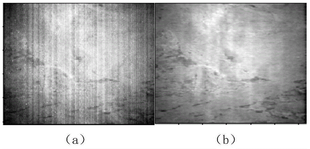
[0056] combine figure 2 , the infrared detector collects the infrared image of the mountain at night at high altitude, and the image size is 320×256;
[0057] Step 1. After the original analog image collected by the infrared detector is converted by A / D, the original digital image is obtained;
[0058] Step 2. Correct the original digital image to obtain the output pixel matrix Y of the n-1th frame after correction n-1 (i, j) and the output pixel matrix Y of the nth frame after correction n (i, j), the correction formula is as follows:
[0059]
[0060] Step 3. Determine the output pixel matrix Y of the n-1th frame after the above correction n-1 The average value of (i, j): the output pixel matrix Y of the n-1th frame after statistical correction n-1 (i, j), and find its average average n , n represents the frame number;
[0061] Step 4. Output the pixel matrix Y for the n-1th frame after correction n-1 The pixel value y of each pixel point of (i, j) n-1 Adjust res...
Embodiment 2
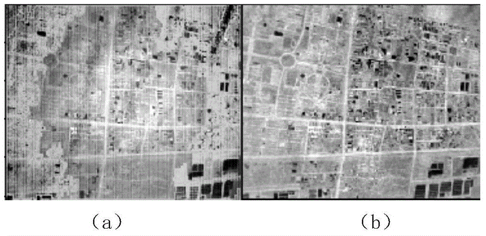
[0080] combine image 3 , the infrared detector collects the infrared image of the overpass shot at night at high altitude, and the image size is 320×256;
[0081] Step 1. After the original analog image collected by the infrared detector is converted by A / D, the original digital image is obtained;
[0082] Step 2. Correct the original digital image to obtain the output pixel matrix Y of the n-1th frame after correction n-1 (i, j) and the output pixel matrix Y of the nth frame after correction n (i, j), the correction formula is as follows:
[0083]
[0084] Step 3. Determine the output pixel matrix Y of the n-1th frame after the above correction n-1The average value of (i, j): the output pixel matrix Y of the n-1th frame after statistical correction n-1 (i, j), and find its average average n , n represents the frame number;
[0085] Step 4. Output the pixel matrix Y for the n-1th frame after correction n-1 The pixel value y of each pixel point of (i, j) n-1 Adjust ...
PUM
Abstract
The invention discloses an infrared image non-uniformity correction method based on scene inter-frame registration. The method comprise following steps: obtaining an original digital image by performing A / D conversion to an original simulation image acquired by an infrareddetector; then performing correction to the original digital image to obtain an output pixel matrix Yn-1(i, j) of a corrected (n-1)th frame and an output pixel matrix Yn(i, j) of a corrected nth frame; performing statistics to the output pixel matrix Yn-1(i, j) of the corrected (n-1)th frame and obtaining its average value averagen; finally, performing updating to o<n+1>(i, j) and g<n+1>(i, j) through the self-adjusting of the output pixel matrix Yn-1(i, j) of the corrected (n-1)th frame, the threshold value ERRn(i, j), and the convergence step length step to achieve non-uniformity correction of the whole image. The method is simple and efficient; convergence rate is high; highly non-uniform images can be corrected by the method; good correction effect can be achieved by the method in different scenes; the method has broad application.
Description
technical field [0001] The technology of the invention belongs to the field of infrared image non-uniformity correction, and in particular relates to an infrared image non-uniformity correction method based on registration between scene frames. Background technique [0002] Infraredradiation enables human beings to expand their vision of nature. In the infrared imaging system, external infrared radiation is transmitted to the infrared detector through the optical system and focused on the thermal sensor. The detector converts the infrared radiation energy into an electrical signal. The signal reflects the intensity of infrared radiation energy, and after amplification, AD sampling and signalprocessing, an observableinfrared image is formed on the display system. [0003] The infrared imaging system uses the difference in surface temperature of the object for imaging. The response of the front-end detector is not absolutely linear, but generally increases with the increas...
Claims
Application Information
Patent Timeline
Application Date:The date an application was filed.
Publication Date:The date a patent or application was officially published.
First Publication Date:The earliest publication date of a patent with the same application number.
Issue Date:Publication date of the patent grant document.
PCT Entry Date:The Entry date of PCT National Phase.
Estimated Expiry Date:The statutory expiry date of a patent right according to the Patent Law, and it is the longest term of protection that the patent right can achieve without the termination of the patent right due to other reasons(Term extension factor has been taken into account ).
Invalid Date:Actual expiry date is based on effective date or publication date of legal transaction data of invalid patent.

